00194398-01.pdf - 第57页
Retrofit instructions SIPLACE HS-60 12/2004 Edition 2.7 Adapting to the size of the substra te 57 : Fit the necessary complete stop rail (s ee table above and Fig . 2.7 - 1). Fig. 2.7 - 1 S top (unit) set 1, 2, 3 and mat…

Retrofit instructions SIPLACE HS-60
2.6 Set the response distance of the proximity switch 12/2004 Edition
56
2.6 Set the response distance of the proximity switch
: Make sure that the active surface of the inductive proximity switch is set back 0.2 mm from the
stop surface of the carriage unit in the hole.
This prevents the proximity switch acting as a stop during the opening movement, and thus
being damaged.
: Correct the position of the proximity switch if necessary (grub screw, size 1 hexagon socket
spanner).
The proximity switch has an LED for checking the switching process.
2.7 Adapting to the size of the substrate
The ceramic substrate centering must be adapted to suit the size of substrate that is to be pro-
cessed in order to ensure 3-point contact of the substrate for centering in the X direction. This is
done by fitting the appropriate stop rail (with 2 ball bearings) and a suitable stop unit (with fixed
roller AND spacer bolt) -> see table below for item numbers.
CAUTION
The stop spacer bolt (set 1 to 3) must not be removed. 2
: Detach the complete stop rail fixing on the X-axis carriage unit (2 hexagon socket head screws
M 3, see Fig. 2.7 - 2 -> 4, 5).
Designation for substrate width Item no.
Stop rail 1, complete
with parallel pin
from 50 mm to 62 mm 00358877-01
Stop rail 2, complete from 62 mm to 106 mm 00358884-01
Stop rail 3, complete from > 106 mm to 140 mm 00358885-01
Stop set 1 (complete
with distance bolt)
from 50 mm to 62 mm 00358874-01
Stop set 2 (complete
with distance bolt)
from 62 mm to 106 mm 00358875-01
Stop set 3 (complete
with distance bolt)
from > 106 mm to 140 mm 00358876-01
Retrofit instructions SIPLACE HS-60
12/2004 Edition 2.7 Adapting to the size of the substrate
57
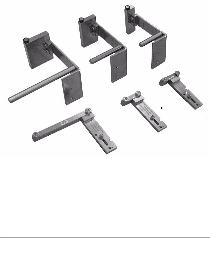
: Fit the necessary complete stop rail (see table above and Fig. 2.7 - 1).
Fig. 2.7 - 1 Stop (unit) set 1, 2, 3 and matching stop rail, complete 1, 2, 3
1. Stop (unit) set 1, fixed stop
2. Stop (unit) set 2, fixed stop
3. Stop (unit) set 3, fixed stop
4. Stop rail 1, 2 and 3, complete (see marking 1, 2 and 3), movable stop
5. Travel limiting parallel pin:
MUST be present on stop rail 1
NOTE:
For substrates 50 mm to 62 mm wide that are more than 50 mm long (e.g. twice as long), the stop
set 1 (fixed stop) is fitted together with the complete stop rail "2" (= movable stop) (see table above
and Fig. 2.7 - 1). 2
: Detach the stop (= stop unit) fixing on the X-axis carriage unit (2 hexagon socket head screws
M3, see Fig. 2.7 - 2 -> 6, 7).
2
3
1
5
4
4
4
Retrofit instructions SIPLACE HS-60
2.7 Adapting to the size of the substrate 12/2004 Edition
58
: Fit the necessary stop unit 1, 2 or 3 (see table above).
2
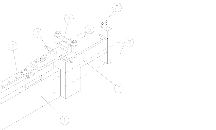
Fig. 2.7 - 2 Matching the ceramic substrate centering to the size of substrate
Key: 2
1. Base unit
2. X carriage unit
3. Fixing bracket for stop rail, 2 hexagon socket head screws M3 x 8
4. Stop rail (according to size of substrate: see table above)
5. 2 hexagon socket head screws M3
6. Stop unit with spacer bolt (according to size of substrate: see table above)
7. Fixing for stop unit: 2 hexagon socket head screws M3
8. Fixed stop roller
2
2
2
2
2
2