00194398-01.pdf - 第61页
Retrofit instructions SIPLACE HS-60 12/2004 Edition 2.9 Circuit diagram 61 2.9 Circuit diagram 2 Fig. 2.9 - 1 Wiring diagram for SIPLACE HS-60 / HF Status Modified Date Name Stand. Orig. Repl. f. Repl. by Sheet Sh. Weite…
Retrofit instructions SIPLACE HS-60
2.8 Pneumatic drawing 12/2004 Edition
60
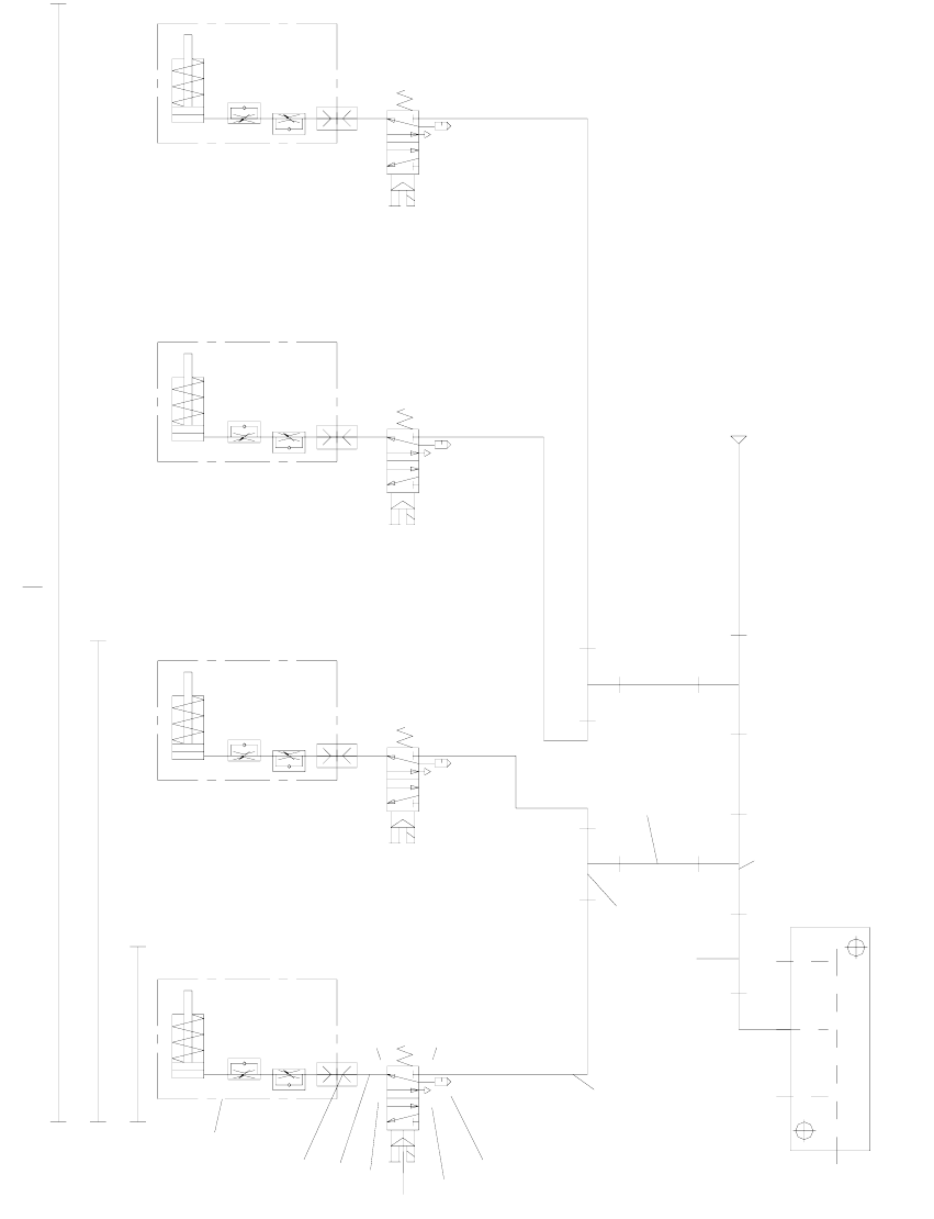
2.8 Pneumatic drawing
2
Fig. 2.8 - 1 Pneumatic drawing for ceramic substrate centering unit, HF series, HS-60, S-27 HM (00119671-010501)
Ø8x1.25
p=5.5 bar
Conveyor air distributor
10
10
5
9
8
7
6
6
5
4
3
2
1
HS60 DC + HF DC
S27HM DC + HS60 + HF
Ceramic substrate
centering assembly
5
1
4
3
2
5
1
4
3
2
5
1
4
3
2
5
1
4
2
3
Lock connections 4 and 5 using the item 10 screws.
S27HM
Retrofit instructions SIPLACE HS-60
12/2004 Edition 2.9 Circuit diagram
61
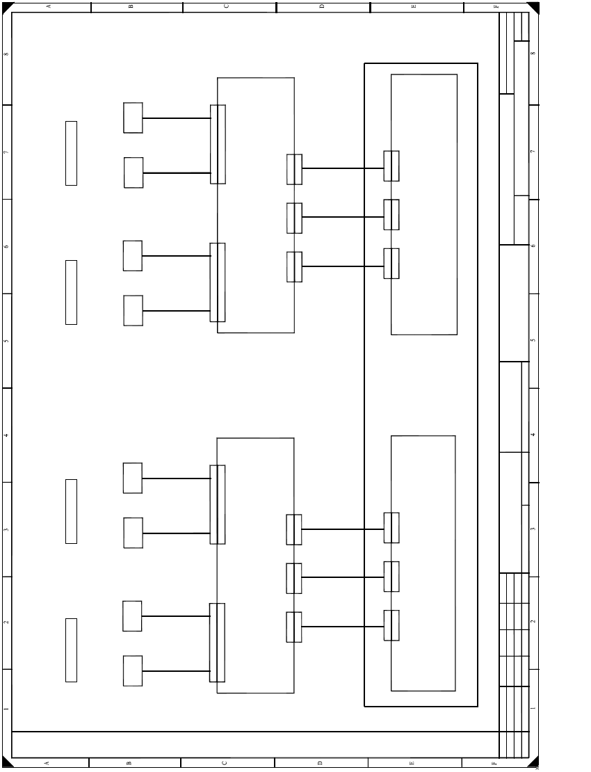
2.9 Circuit diagram
2
Fig. 2.9 - 1 Wiring diagram for SIPLACE HS-60 / HF
Status Modified Date Name Stand. Orig. Repl. f. Repl. by
Sheet
Sh.
Weitergabe sowie Vervielfältigung dieser Unterlage,Ver-
wertung und Mitteilung ihres Inhalts nicht gestattet, soweit
nicht ausdrücklich zugestanden. Zuwiderhandlungen ver-
pflichten zu Schadenersatz. Alle Rechte vorbehalten, ins
besondere für den Fall der Patenterteilung oder GM-Eintragung
Proprietary date, company confidential. All rights reserved.
Confie a titre de secret d´entreprise. Tous droits reserves.
Comunicado como segredo empresarial. Reservados todos os direilos.
Confiado como secrete industrial. Nos reservamos todos los derechos.
SIPLACE HF series
Placement area 2
Overview: Ceramic substrate centering
dual conveyor
00119470-010101LD3
1 .
1 .
Schn
Schn
Schneider
Schn
1 .
22.04.2002
Document status
Product status
Function status Date
Author
Check.
SD EA1
22.04.2002
22.04.2002
22.04.2002
X34kt
X34kt
Sensor
Ceramic
substrate cent. 1
(Conveyor 1)
Ceramic substrate centering, conveyor track 1
B 1
Ceramic substrate centering, conveyor track 2
Z 1
Valve
Ceramic
substrate cent. 1
(Conveyor 1)
00 369722 - W1
Control assy, PCB conveyor (dual conveyor: 00365544-xx)
Conversion board, assembly trough, track 1 (kt)
00359425
X12
X12
X11
X11
X52
X52
X51
X51
Conveyor control (ao)
00370397
X12
X12
X11
X11
Extension card, conveyor control (ap)
00370398
00 369722-W2
X35kt
X35kt
Sensor
Ceramic
substrate cent. 2
(Conveyor 1)
B 2
Z 2
Valve
Ceramic
substrate cent. 2
(Conveyor 1)
00 369722 - W1
00 369722-W2
X34ku
X34ku
Sensor
Ceramic
substrate cent. 4
(Conveyor 2)
B 4
Z 4
Valve
Ceramic
substrate cent. 4
(Conveyor 2)
00 369722 - W1
Conversion board, assembly trough, track 2 (ku)
00359425
X52
X52
X51
X51
00 369722-W2
X35ku
X35ku
Sensor
Ceramic
substrate cent. 3
(Conveyor 2)
B 3
Z 3
Valve
Ceramic
substrate cent. 3
(Conveyor 2)
00 369722 - W1
00 369722-W2
00 363420
00 363419
00 363433
00 363432
1
1
Overview: Connecting the ceramic substrate centering
X13
X13
X53
X53
00 363431
X13
X13
X53
X53
00 363434
Placement area 1 Placement area 2 Placement area 1
Retrofit instructions SIPLACE HS-60
2.10 Activating the option 12/2004 Edition
62
2.10 Activating the option
2.10.1 Overview
All though the fully installed "mechanical ceramic substrate centering" option hardware is auto-
matically detected by the software due by the presence of the coding plug (plug-in connection
between the option and the conveyor control), it still has to be activated in the SITEST program.
The mechanical ceramic substrate centering is always combined with fiducial position detection
on the substrate.
The position detection is carried out with the PCB vision camera with normal lighting or the
optional oblique lighting. If the optional multi-color PCB camera is used on the machine, rather
than the above PCB vision camera, then the fiducials are always centered with this camera by
default. The oblique lighting option is not used in this case.
Please note: 2
– If the mechanical ceramic substrate centering hardware has been installed, it must also be ac-
tivated in the "Machine Configuration" menu.
– When the mechanical ceramic substrate centering is deactivated in the Machine Configuration
menu, then it must first be fully removed from both processing areas of the affected conveyor,
i.e. the plug-in connections on the option must also be detached from the conveyor control.
The conveyor modules must also be converted on the PCB conveyor in parallel.
2
2
2
2
2
2
2
2
2
2
2
2