DuraBlue II Customer Product Manual.pdf - 第104页
Service 5-14 Part 1126931_01 2018 Nordson Corporation Replace the Adhesive Filter 1. Relieve the system pressure. Refer to Relieving System Pressure at the beginning of this section. 2. Use an 8 mm ( 5 / 16 -inch) hex-…
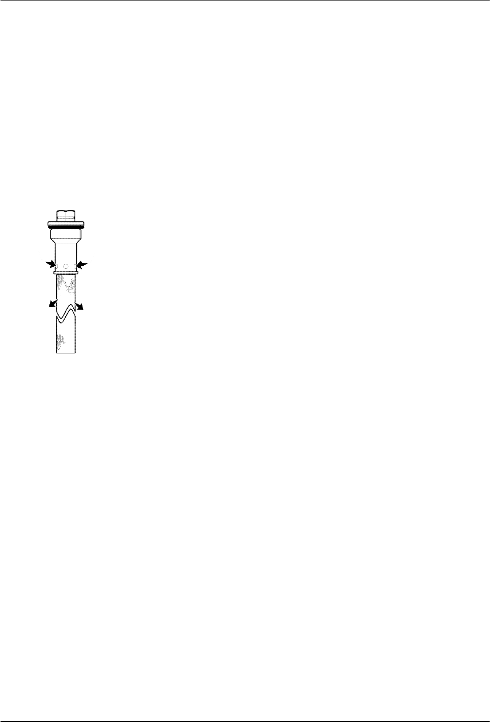
Hot melt flow path
Service
5-13
Part 1126931_01
2018 Nordson Corporation
Replacing the Adhesive Filter
DuraBlue II melters are equipped with a 100-mesh (0.15-mm) disposable
hot melt adhesive filter. The adhesive filter removes debris and char from
the hot melt as it flows from the tank. Hot melt flows from the inside to the
outside of the filter, trapping contaminants inside the filter. There is no need
to back-flush or clean the filter.
When the filter reaches the end of its service life, it should be replaced. The
factors that determine the service life of the filter are:
the type, grade, and purity of the solid-form hot melt
the set point temperature of the tank
the period of time that the hot melt remains in the tank
The filter should also be replaced when making the change to a different type
or grade of hot melt.
To determine the optimal service life for the filter, monitor and compare the
total number of hours that the heaters are on with observations of:
the purity of the dispensed hot melt
increases in operating pressure
the frequency of applicator nozzle replacement or cleaning
As an aid to ensuring that the filter is replaced at the end of its service life, the
melter is equipped with a service LED that turns on at the end of a
customer-defined time period. Refer to Setting Up the Melter in Section 3,
Installation, for information about the service interval time.
Service
5-14
Part 1126931_01
2018 Nordson Corporation
Replace the Adhesive Filter
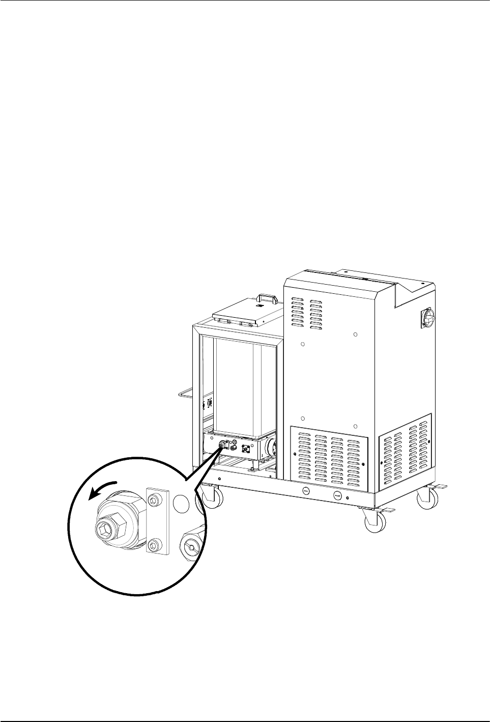
1. Relieve the system pressure. Refer to Relieving System Pressure at the
beginning of this section.
2. Use an 8 mm (
5
/
16
-inch) hex-head wrench or an adjustable wrench to
loosen (counterclockwise) and then remove the adhesive filter.
3. Properly dispose of the old filter.
4. Confirm that the O-ring on the new adhesive filter is in good condition
(100-mesh filter is P/N 1028305).
NOTE: 50- and 150-mesh filters are also available (P/Ns 1021941 and
1034720).
5. Screw the filter into the pump body and then tighten the filter to 4.5 Nm
(40 in.-lb).
6. Resume normal operation.
Service Kit, for P/N refer to Section 7, Parts.
Figure 5‐9 Turning the adhesive filter counterclockwise to remove
Adjusting the set screw
+*
Service
5-15
Part 1126931_01
2018 Nordson Corporation
Pressure Control Valve
Replace the Pressure Control Valve
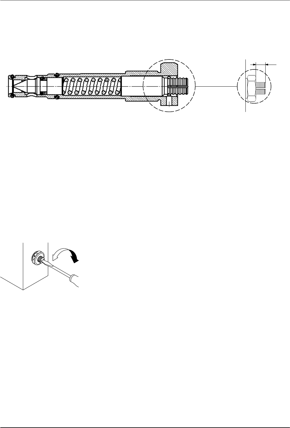
X
Figure 5‐10 Pressure control valve set screw insertion depth
NOTE: Screw in only when valve and pump are warm and material is soft.
1. Ensure the melter is at operating temperature.
2. Relieve system pressure. Refer to Section 1, Safety.
3. Measure and make a note of the insertion depth of the set screw
(dimension X). This way the insertion depth can be replicated after
reassembly.
4. To prevent adhesive from leaking into the valve bore, drain the tank.
Refer to Draining Material from the Tank later in this section as needed.
5. Remove the old pressure control valve.
6. Apply high temperature grease to all threads and O-rings.
7. Slide the valve into the hole and tighten with torque wrench
(15 N•m / 133 in.-lb).
8. Adjust the setting screw to the recorded dimension X.
Turning to the right increases material pressure.
Turning to the left decreases material pressure.