DuraBlue II Customer Product Manual.pdf - 第107页
Service 5-17 Part 1126931_01 2018 Nordson Corporation Cleaning the Tank Draining Material from the Tank Pump material out of the melter. CAUTION! Do not feed charred material though the applicator. Particles can block …
Service
5-16
Part 1126931_01
2018 Nordson Corporation
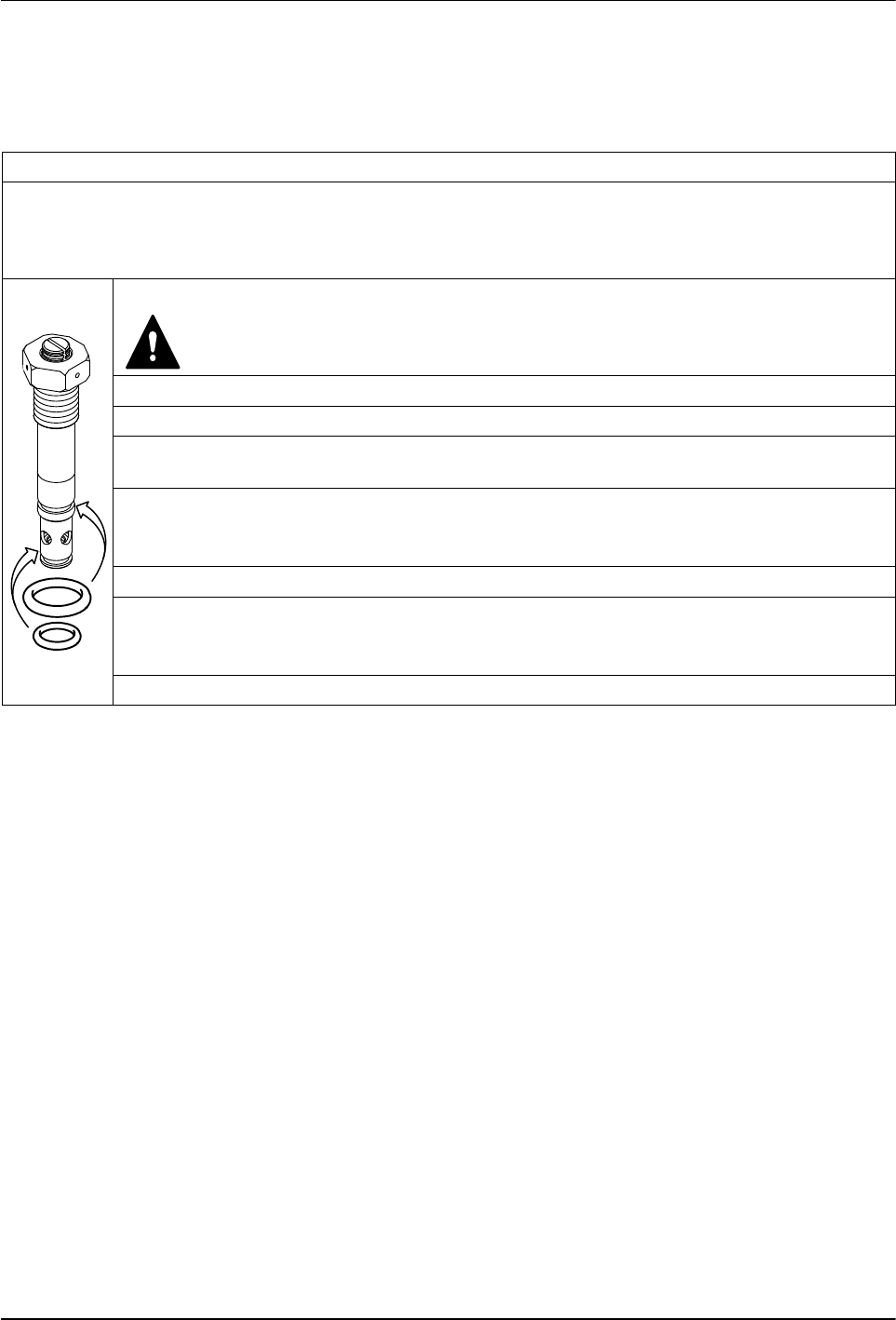
Pressure/Circulation Control Valve Service Kit
Each kit contains two O‐rings and high‐temperature grease.
Service kit P/N: 394600
Required tools:
Open‐jawed wrench, size 24
Pliers
Torque wrench
1. Heat melter to operating temperature.
WARNING: Hot! Risk of burns. Wear appropriate protective
clothing/equipment.
2. Relieve melter pressure.
3. Measure insertion depth. Refer to Pressure Control Valve.
4. Use an open‐jawed wrench to screw out the pressure control valve, then extract with a
pliers.
5. Remove old O‐rings and disassemble and clean pressure control valve. Refer to Section
7, Parts, for a detailed drawing.
NOTE: Disassemble valve only when warm.
6. Install new O‐rings. Apply grease to all threads and O‐rings.
7. Guide pressure control valve into the hole when the melter is warm and tighten with
torque wrench.
Starting torque: 15 Nm (133 in.‐lb)
8. Adjust set screw. Refer to Pressure Control Valve.
Service
5-17
Part 1126931_01
2018 Nordson Corporation
Cleaning the Tank
Draining Material from the Tank
Pump material out of the melter.
CAUTION! Do not feed charred material though the applicator. Particles can
block the applicator. Instead unscrew hose (refer to Section 3, Installation).
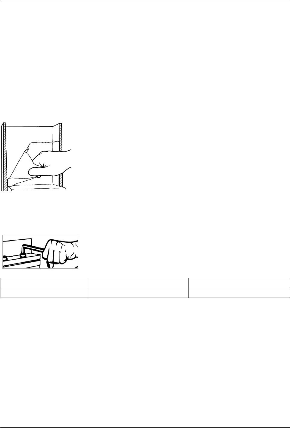
Cleaning the Tank by Hand
Cold material can usually be peeled off of the sides of the tank. If necessary,
first heat tank to material softening temperature, usually approximately
70 ° C / 158 ° F.
NOTE: The inside of the tank is release coated. Do not use metallic tools to
clean. Do not use wire brushes! This could damage the release coating.
Tightening the Fixing Screws
Heating and cooling that occurs during daily operation can cause the fixing
screws to loosen. Tighten screws as indicated in the table below.
NOTE: Tighten fixing screws only using a torque wrench and when the
melter is cold.
Connection
Thread Torque
Tank/manifold M 6 6-8 Nm / 53-71 in.‐lb
Service
5-18
Part 1126931_01
2018 Nordson Corporation
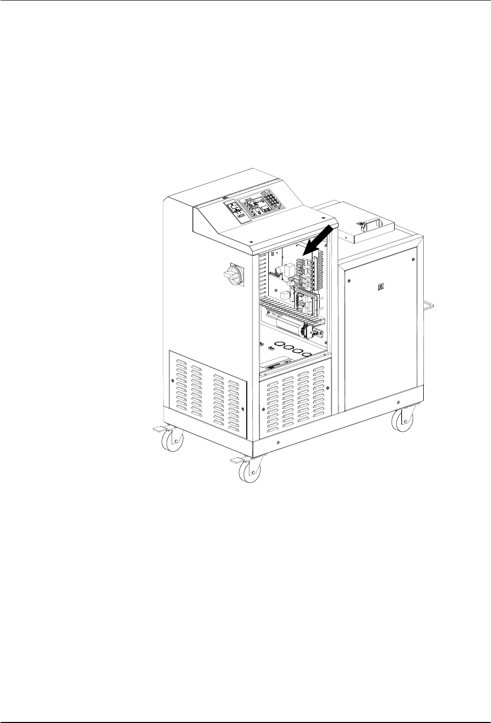
Main PCA Board
Replace the Main PCA Board
1. Disconnect power to the melter at the local disconnect switch.
2. Switch the melter off.
3. See Figure 5‐11. Open the electrical enclosure access panel and locate
the main PCA board.
Figure 5‐11 Location of the main PCA board
4. Disconnect all of the power and control cables from the board.
5. Remove the four fastening screws that hold the board on the mounting
studs and then remove the board.
NOTE: Before installing the new board, you must ensure that the board
is properly configured for the type of temperature sensors present on the
melter. If the melter uses 100‐ohm platinum sensors, the jumpers
connected to the JP1 terminal on the old board must be removed and
then installed on the new board. Figure 5‐12 shows the location of
terminal JP1 on the main PCA board. Figures 5‐13 and 5‐14 show the
jumpers installed and not installed, as appropriate for each type of melter.