DuraBlue II Customer Product Manual.pdf - 第110页
Service 5-20 Part 1126931_01 2018 Nordson Corporation Replace the Main PCA Board (contd) 6. If 100‐ohm platinum sensors are present on the melter: a. Locate the JP1 terminal on the replacement board. NOTE: For 120‐ohm …
Service
5-19
Part 1126931_01
2018 Nordson Corporation
R108
R7
R65
C55
R92
C6
C66
C32
C74
R127
R88
R72
R9
R61
R14
R11
DS5
R82
R49
D10
R79
R12
R102
R69R90
DS16
R130
R87
RV13
RN3
R103
R53
Q5
Q12
R78R59
+
C82
Q24
R129
R73
C80
C22
RV5
RN9
C79
R56
C69
R100
C84
R34
C8
C3
RV7
C4
RV12
C72
RV11
C10
C23
C25
C26
R115 R112
Q7
Q9
C28
C29
R67
R66
R71
R117
L4
R58
R52
R36
R33
C53
RV6
C1
R80
R136
R133
D8
R134
U5
C7
RN10
R106
R51
R57
Q14
R39R42
R83
R37
R74
U12
R44R45
C77
R38
R4
R3
Q26
Q17
R99
Q18
R121
R101
R8
R118
Q25
R6
DS3
C47
DS4
L3
R96
C43
C44
R70
Q23
R93 R5
R55
Q8
R16
R10
DS7
D12
C54
R84
R85
Q22
R17
R109
Q10
DS6
R76
R122
R131
D11
R132
Q13
1
J2
R86
RV10
R26
XP5
+
C58
R111
R123
U26
C51
L2
U4
+
C12
RN5
R89
XP6
C31
RN6RN4
DS13
R104
R48
DS8
DS12
R35
R60
DS10
DS11
R116
R94
Q16
R40
C39
U23
D5
R2
R43R46
C2
R128
R1
+
C40
R75
R119
R120
C37
C18
RN1
C15
RN11
C17
R95
Q20
Q19
C21 C20
R15
RN2
R77
R113
1
X2
C70 C71
R62
1
X3
D3
R50
C46
C83
C68C73
R97
R124
U21
C48 C49
RV9
C61
XP2
R110
R98
C36
C24
C9
C5
U3
U25
DS15
+
C35
DS14
DS9
C27
C30
C75
U2
+
C16
DS17
R13
C67
C62
RV1
R68
RV3
C76
C11
R91
D4
RN7
C60
R81
R20
Q15
DS2
XT1
C42
C41
RV8
C50
D17
R19
R107
U20
U10
U19
U15
U18
U9
1
XP3
RV2
X7
D1
D6
RV4
1
XP4
C65
D2
D7
D14
U1
U17
U14
JP2
C63
R22
R63
U16
C56
D16
R18
51
26
JP1
1
33
J1
1
X1
C52
C64
C45
L1
R114 R105
U24
U13
3
12
1
X5
U7
T1
HSNK1
C78
+
C59
X6
XP1
D18
+
C57
3
12
1
X4
K1
++
U22
F3
F4
F6 F5
F1
F2
F11
F12
F7
F8
F10
F9
5A
10A
6.3A
2A
2A
5A
10A
6.3A
6.3A
6.3A 6.3A
6.3A
+
Q6 Q11
C19
R54
R47
R53
R135
R41
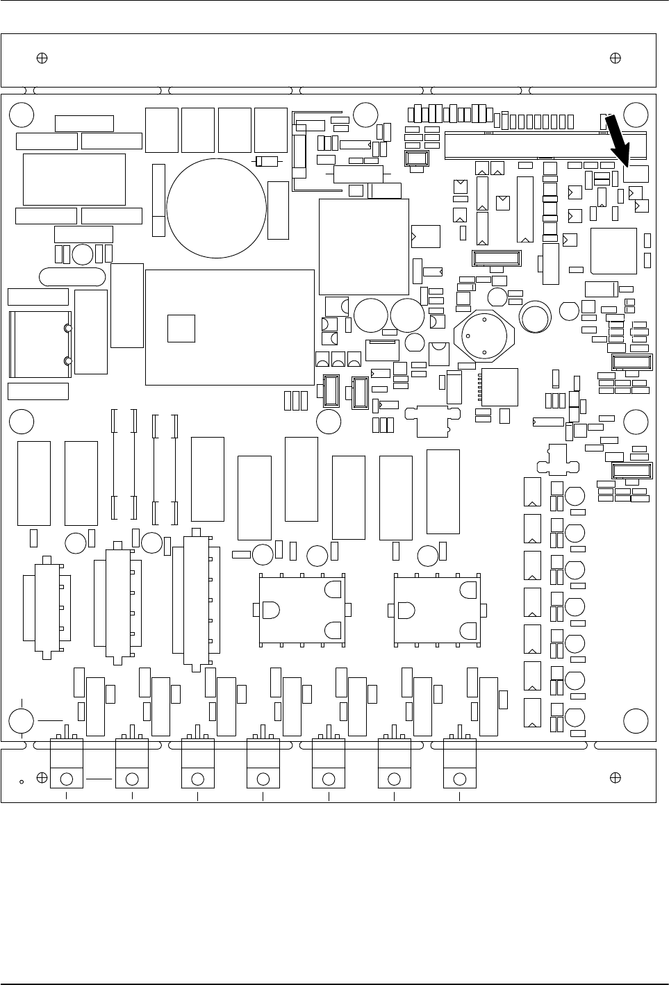
Figure 5‐12 Location of the JP1 terminal on the main PCA board
Service
5-20
Part 1126931_01
2018 Nordson Corporation
Replace the Main PCA Board (contd)
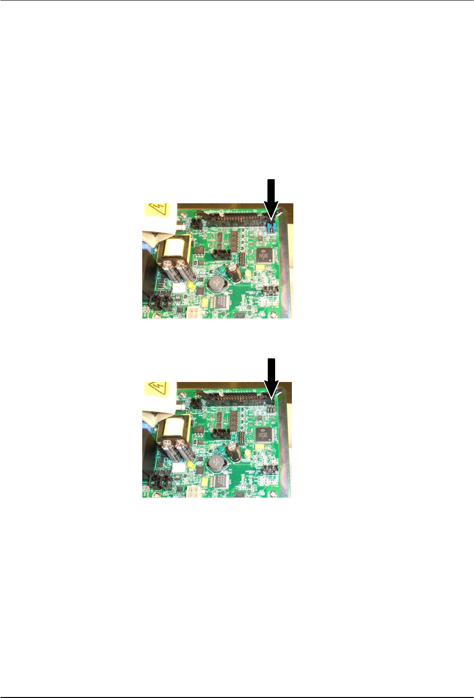
6. If 100‐ohm platinum sensors are present on the melter:
a. Locate the JP1 terminal on the replacement board.
NOTE: For 120‐ohm nickel melters, temperature sensor jumpers are
not required in this location, as shown in Figure 5‐14.
b. Install one of the jumpers removed from the old board between
terminals 1 and 2.
c. Install the second jumper between terminals 5 and 6. Figure 5‐13
shows the jumpers installed.
Figure 5‐13 100‐ohm platinum melter—jumpers installed
Figure 5‐14 120‐ohm nickel melter—no jumpers installed
7. Install the replacement board inside the melter electrical enclosure using
the fastening screws removed previously.
8. Reconnect all of the power and control cables to the replacement board
and close the electrical access panel.
9. Restore power to the melter and switch the melter on. Verify that the
melter starts normally.

Service
5-21
Part 1126931_01
2018 Nordson Corporation
Maintenance Record Form
Melter part Date / Name Date / Name Date / Name
Pump
Motor / gear box
Fixing screws on pump and
tank
Air filter
Tank
Pressure control valve
Filter cartridge