DuraBlue II Customer Product Manual.pdf - 第120页
Troubleshooting 6-8 Part 1126931_01 2018 Nordson Corporation Motor Drive Faults The display on the motor drive located inside the electrical enclosure alerts the operator to abnormal motor drive/motor operation. Motor …
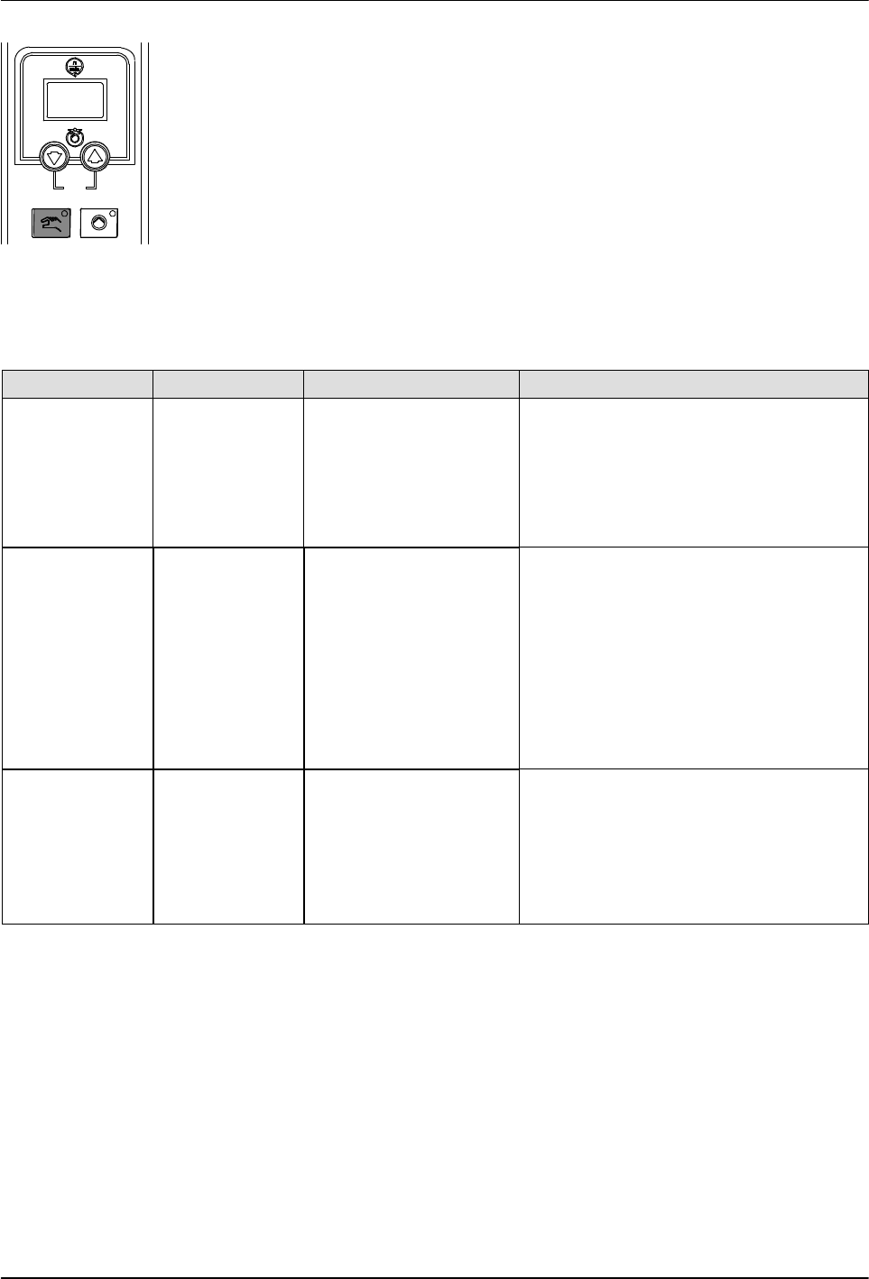
Pump mode key and LED
Troubleshooting
6-7
Part 1126931_01
2018 Nordson Corporation
5. Press the Pump mode key to save the value and move to the next
parameter.
6. Repeat steps 3-4 for each parameter you want to change.
7. To exit the setup mode, press the Pump mode key one additional time
after the last parameter has been displayed.
Table 6‐3 Motor Control Parameter Factory Settings
Parameter Factory Setting Description Explanation
SEt 94 Maximum pump rpm This parameter controls the increment of
change in motor speed that occurs upon
each press of a pump speed up or down
arrow key when the melter is operating in
the manual mode. To change the rpm in
increments of 1, set this parameter to the
maximum pump rpm.
Srt 0 Motor start mode This parameter controls the method used
to start the motor(s):
To start a motor by pressing the pump
start/stop key on a motor control panel,
enter 0. This setting is typically used if a
melter has more than one motor.
If you want a motor to start when the
pump enable signal is activated, enter 1.
This setting is typically used if a melter
has only one motor.
LoS 0 Minimum pump speed
in gear‐to‐line mode
If the melter will be operated in the
manual mode, enter 0.
If the melter will operated in the
gear‐to‐line mode, enter a minimum line
speed. The motor speed will not fall
below this valve even if the signal drops
to 0 V.
Troubleshooting
6-8
Part 1126931_01
2018 Nordson Corporation
Motor Drive Faults
The display on the motor drive located inside the electrical enclosure alerts
the operator to abnormal motor drive/motor operation. Motor drive faults
cause the pump to stop, refer to the motor drive Error Messages given later.
To clear a motor drive fault, correct the problem that caused the fault and
then remove power from the motor drive by turning the heaters off and wait
until the motor drive display is completely blank.
1
2
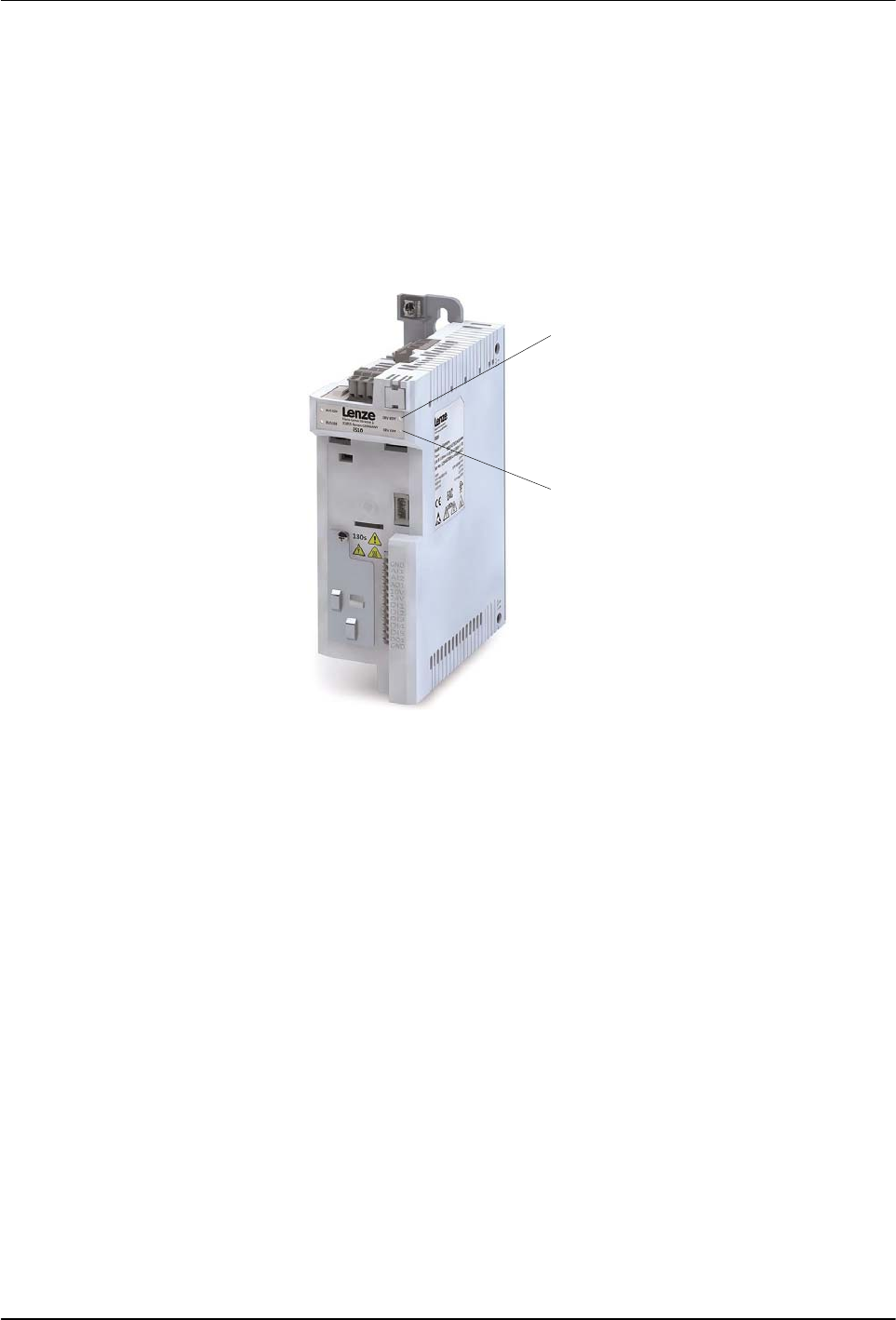
Figure 6‐1 Motor drive power LED and display
1. Motor drive Ready (RDY) LED 2. Motor drive Error (ERR) LED
Troubleshooting
6-9
Part 1126931_01
2018 Nordson Corporation
LED Status Display
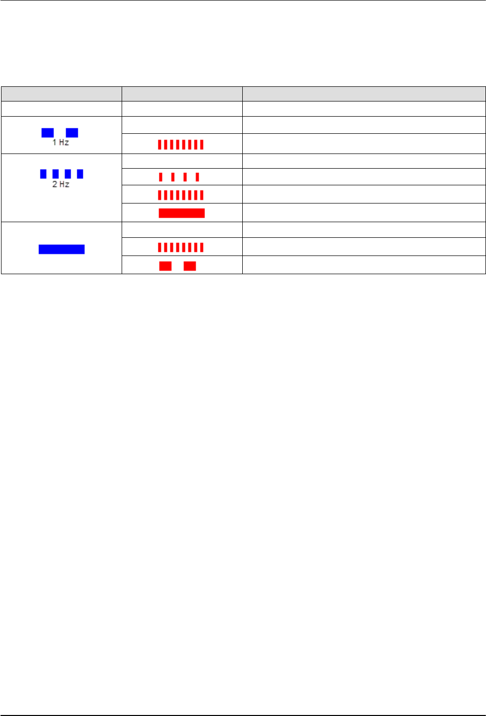
The motor drive has two LEDs, READY (RDY) and ERROR (ERR), see LED
location on Figure 6‐1. Refer to the following table to identify the motor drive
state:
RDY (Blue) ERR (Red) Motor Drive State
– – No supply voltage
–
STO active
STO active, warning active
– Motor drive inhibited
Motor drive inhibited, DC Voltage not On OR Reset
Motor drive inhibited, Warning active
Motor drive inhibited, Fault active
–
Motor drive released, drive running OR Quick Stop
Motor drive released, drive running, Warning active
Motor drive released, Trouble reaction active