DuraBlue II Customer Product Manual.pdf - 第170页
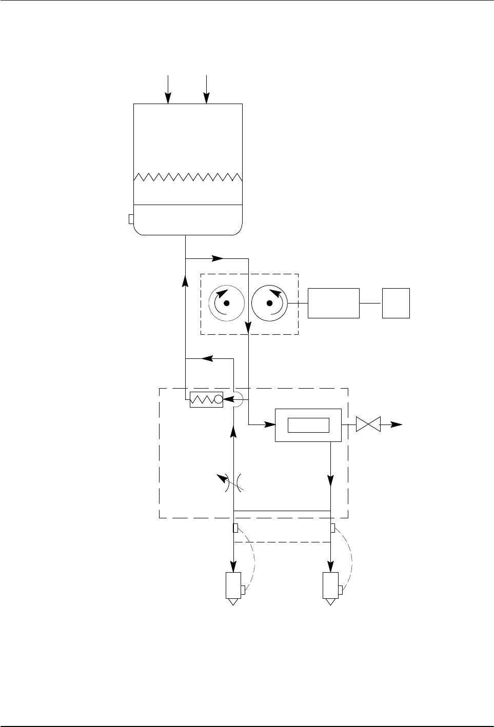
Technical Data 8-4 Part 1126931_01 2018 Nordson Corporation Hydraulic Schematic HOPPER GRID ADHESIVE GEAR FILTER PUMP CV PRV MOTOR CONTROL DRAIN VALVE MOTOR Figure 8-1 Hydraulic system schematic

Technical Data
8-3
Part 1126931_01
2018 Nordson Corporation
Electrical Schematics
Refer to the electrical schematics provided with the melter.

Calculating Melter Power Requirements
A-1
Part 1126931_01
2018 Nordson Corporation
Appendix A
Calculating Melter Power Requirements
Before locating the melter on the production floor or attaching hoses and
guns to the melter, you must calculate the electrical power required by the
hoses and guns and confirm that the required power does not exceed
maximum allowable wattages. Properly calculating melter power
requirements will prevent damage to the melter and identify the maximum
allowable distance between the melter and the point at which the hot melt is
dispensed.
The following three maximum wattages must be considered when calculating
melter power requirements.
Single‐component maximum — The wattage of any single hose or
gun
Hose/gun pair maximum — The combined wattage of any hose and
gun (hose/gun pair)
Two hose/gun pair maximum — The combined wattage of
hose/gun pairs 1 and 2 or hose/guns pairs 3 and 4
If your Nordson representative has already calculated the hose/gun power
requirements and confirmed that the maximum allowable wattages will not be
exceeded, then no further calculation is necessary. However, you should
re‐evaluate the hose and gun power requirements before you:
add a new hose or gun to the melter that was not factored into the
original wattage evaluation
replace an existing hose with a longer hose or an existing gun with a
larger gun