DuraBlue II Customer Product Manual.pdf - 第23页
Introduction 2-3 Part 1126931_01 2018 Nordson Corporation Key Components Figure 2‐1 provides the name and the location of key melter components. 3 1 7 6 2 5 4 11 10 9 2 8 Figure 2‐1 Key melter components 1 Control pane…

Introduction
2-2
Part 1126931_01
2018 Nordson Corporation
Examples of Unintended Use
The melter may not be used under the following conditions:
In defective condition
Without insulation blanket and protective panels
With electrical cabinet door open
With tank lid open
In a potentially explosive atmosphere
When the values stated under Technical Data are not complied with.
The melter may not be used to process the following materials:
Polyurethane hot melt adhesive (PUR)
Explosive and flammable materials
Erosive and corrosive materials
Food products
Residual Risks
In the design of the unit, every measure was taken to protect personnel from
potential danger. However, some residual risks can not be avoided:
Risk of burns from hot material.
Risk of burns when filling the tank, from the tank lid, and from the tank lid
supports.
Risk of burns when conducting maintenance and repair work for which
the melter must be heated up.
Risk of burns when attaching and removing heated hoses.
Material fumes can be hazardous. Avoid inhalation.
Risk of damage to cables/lines belonging to the customer, if they were
installed such that they come into contact with hot or rotating parts.
The safety valve may malfunction due to hardened or charred material.
Introduction
2-3
Part 1126931_01
2018 Nordson Corporation
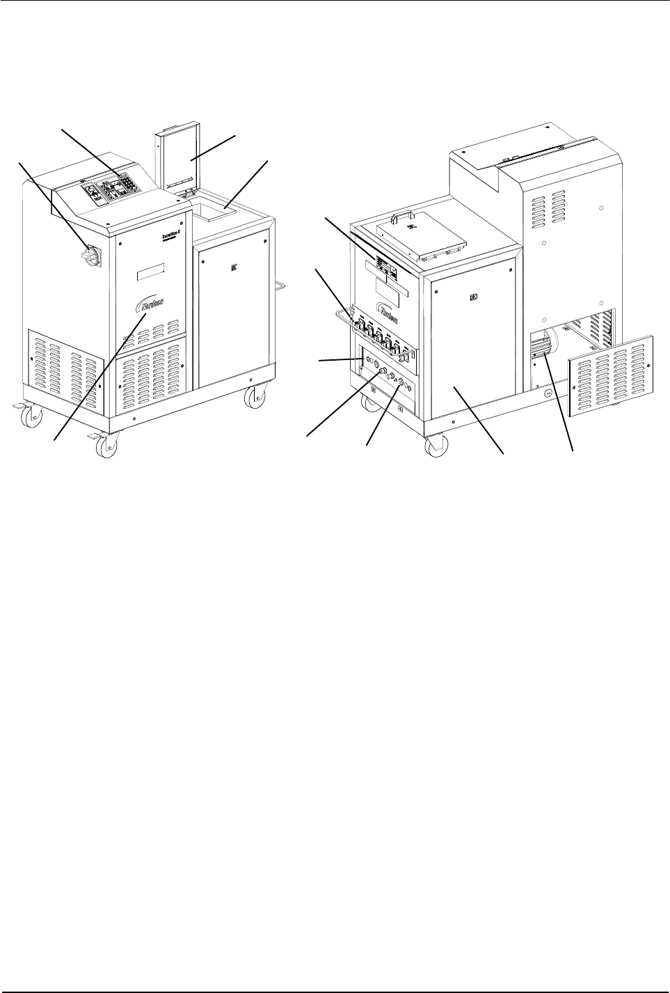
Key Components
Figure 2‐1 provides the name and the location of key melter components.
3
1
7
6
2
5
4
11
10
9
2
8
Figure 2‐1 Key melter components
1 Control panel (see Figure 2‐3)
2 Protective panel, removable
3 Tank lid
4 Main power switch
5 Motors/pumps
6 Drain valve
7 Pressure control valve
8 Manifold
9 Hose receptacles
10 ID plate
11 Tank
Introduction
2-4
Part 1126931_01
2018 Nordson Corporation
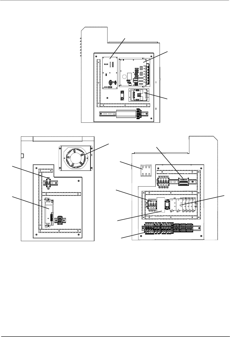
Electrical Components
3
1
7
6
5
11
10
9
2
8
2
4
Figure 2‐2 Key electrical components
1 Main board
2 Circuit breakers
3 Solid state relay
4 Fan
5 Motor controller
6 Signal conditioner
7 Expansion board
8 Power module
9 Main switch
10 Distribution block
11 Contactor
Note: The central processing unit is not shown in this illustration. Refer to Section 7, Parts.