DuraBlue II Customer Product Manual.pdf - 第24页
Introduction 2-4 Part 1126931_01 2018 Nordson Corporation Electrical Components 3 1 7 6 5 11 10 9 2 8 2 4 Figure 2‐2 Key electrical components 1 Main board 2 Circuit breakers 3 Solid state relay 4 Fan 5 Motor controlle…
Introduction
2-3
Part 1126931_01
2018 Nordson Corporation
Key Components
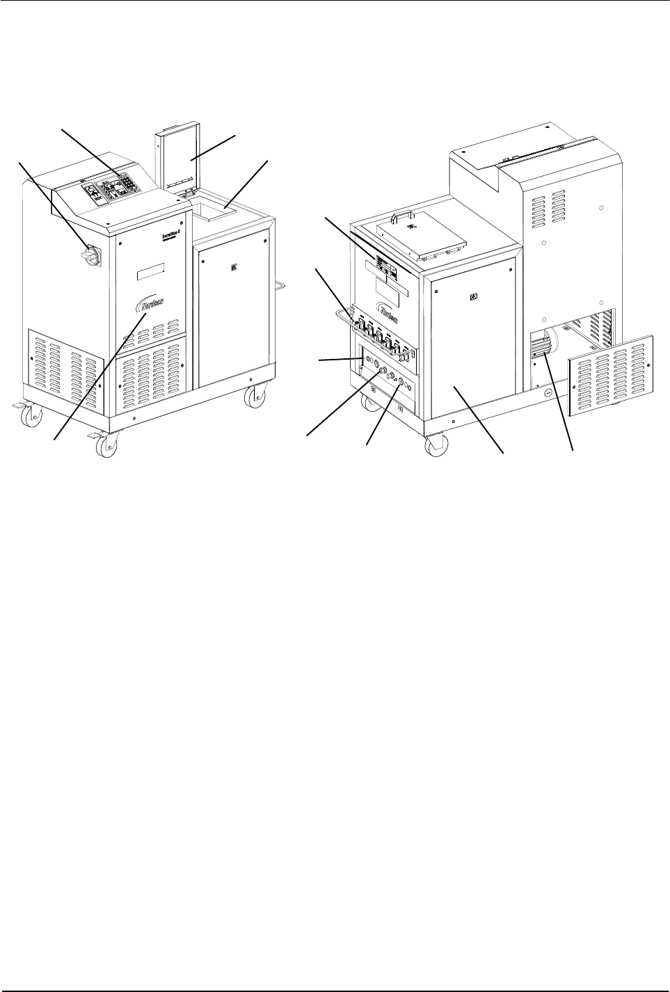
Figure 2‐1 provides the name and the location of key melter components.
3
1
7
6
2
5
4
11
10
9
2
8
Figure 2‐1 Key melter components
1 Control panel (see Figure 2‐3)
2 Protective panel, removable
3 Tank lid
4 Main power switch
5 Motors/pumps
6 Drain valve
7 Pressure control valve
8 Manifold
9 Hose receptacles
10 ID plate
11 Tank
Introduction
2-4
Part 1126931_01
2018 Nordson Corporation
Electrical Components
3
1
7
6
5
11
10
9
2
8
2
4
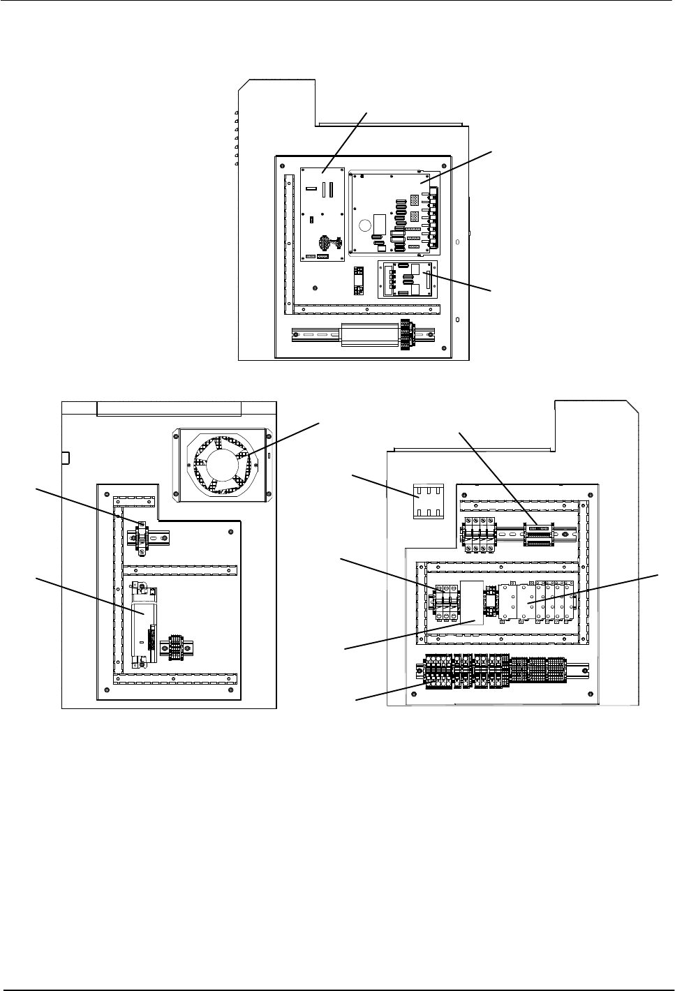
Figure 2‐2 Key electrical components
1 Main board
2 Circuit breakers
3 Solid state relay
4 Fan
5 Motor controller
6 Signal conditioner
7 Expansion board
8 Power module
9 Main switch
10 Distribution block
11 Contactor
Note: The central processing unit is not shown in this illustration. Refer to Section 7, Parts.
Introduction
2-5
Part 1126931_01
2018 Nordson Corporation
Control Panel
1 2
1110 12 13
3 4
14
15
1716
5
6
7
8
9
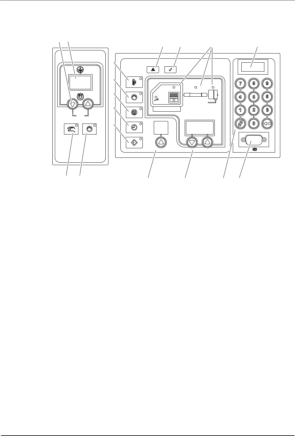
Figure 2‐3 Control panel (melter control panel and two motor control panels shown)
1 Pump speed arrow keys
2 Pump speed display (rpm)
3 Pump mode key/LED
4 Pump enable key/LED
5 Standby key/LED
6 Master pump enable key/LED
7 Heaters key/LED
8 Clock key/LED
9 Setup key/LED
10 Fault light
11 Ready light
12 Component keys/LEDs
13 Control switch
14 Left display and arrow key
15 Right display and arrow keys
16 Numeric keypad
17 Serial port