DuraBlue II Customer Product Manual.pdf - 第25页
Introduction 2-5 Part 1126931_01 2018 Nordson Corporation Control Panel 1 2 11 10 12 13 3 4 14 15 17 16 5 6 7 8 9 Figure 2‐3 Control panel (melter control panel and two motor control panels shown) 1 Pump speed arrow ke…
Introduction
2-4
Part 1126931_01
2018 Nordson Corporation
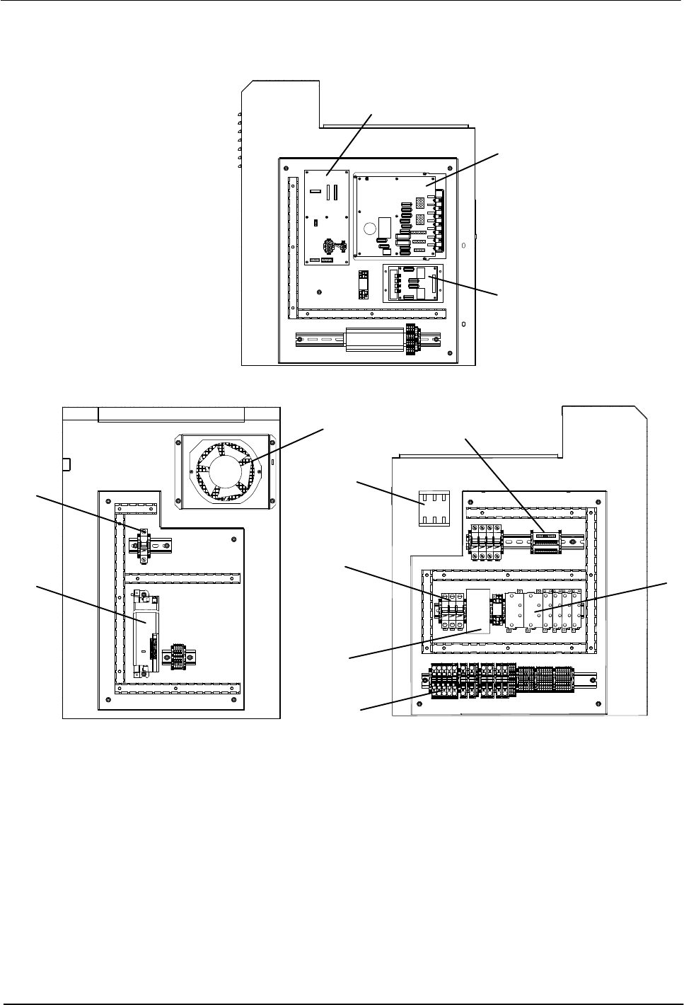
Electrical Components
3
1
7
6
5
11
10
9
2
8
2
4
Figure 2‐2 Key electrical components
1 Main board
2 Circuit breakers
3 Solid state relay
4 Fan
5 Motor controller
6 Signal conditioner
7 Expansion board
8 Power module
9 Main switch
10 Distribution block
11 Contactor
Note: The central processing unit is not shown in this illustration. Refer to Section 7, Parts.
Introduction
2-5
Part 1126931_01
2018 Nordson Corporation
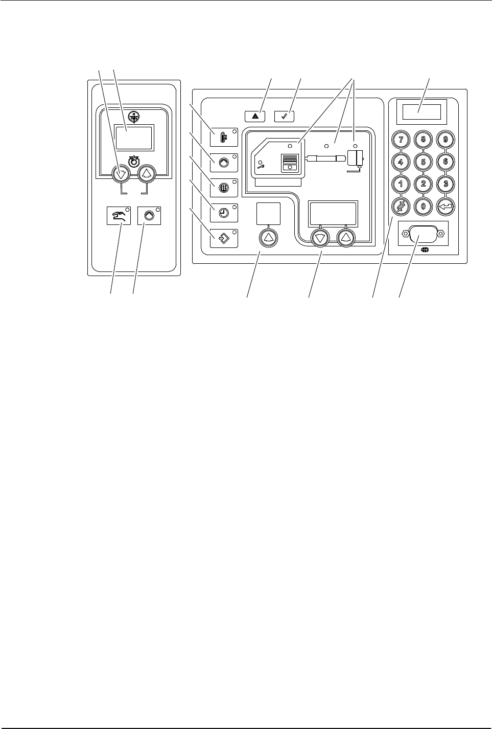
Control Panel
1 2
1110 12 13
3 4
14
15
1716
5
6
7
8
9
Figure 2‐3 Control panel (melter control panel and two motor control panels shown)
1 Pump speed arrow keys
2 Pump speed display (rpm)
3 Pump mode key/LED
4 Pump enable key/LED
5 Standby key/LED
6 Master pump enable key/LED
7 Heaters key/LED
8 Clock key/LED
9 Setup key/LED
10 Fault light
11 Ready light
12 Component keys/LEDs
13 Control switch
14 Left display and arrow key
15 Right display and arrow keys
16 Numeric keypad
17 Serial port
Introduction
2-6
Part 1126931_01
2018 Nordson Corporation
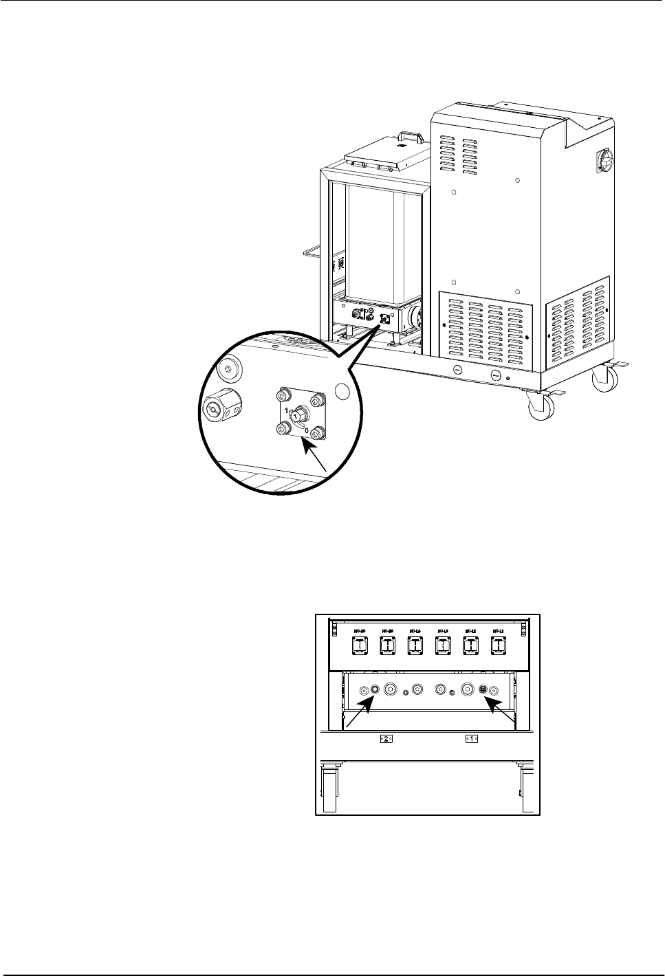
Tank Isolation Valve
The tank isolation valve allows replacement of the pump without first
emptying the tank.
Figure 2‐4 Location of the tank isolation valve
Pressure Control Valves
The manual pressure control valves can be adjusted from 0-90 bar.
Figure 2‐5 Location of the pressure control valves