DuraBlue II Customer Product Manual.pdf - 第27页
Introduction 2-7 Part 1126931_01 2018 Nordson Corporation Modes of Operation DuraBlue II adhesive melters operate in the following modes. Automatic Scan (Normal Mode) The melter automatically checks and displays the cu…
Introduction
2-6
Part 1126931_01
2018 Nordson Corporation
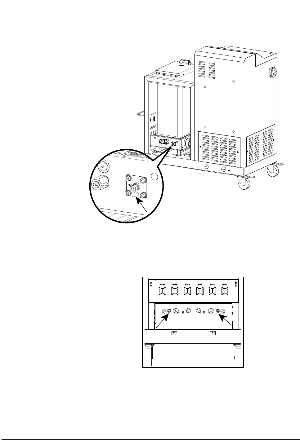
Tank Isolation Valve
The tank isolation valve allows replacement of the pump without first
emptying the tank.
Figure 2‐4 Location of the tank isolation valve
Pressure Control Valves
The manual pressure control valves can be adjusted from 0-90 bar.
Figure 2‐5 Location of the pressure control valves

Introduction
2-7
Part 1126931_01
2018 Nordson Corporation
Modes of Operation
DuraBlue II adhesive melters operate in the following modes.
Automatic Scan (Normal Mode)
The melter automatically checks and displays the current temperature of the
tank, hoses, and guns to confirm that they are within their pre‐defined
temperature range. By default, the melter is always in the automatic scan
mode unless it is placed into another operating mode.
Standby
The temperatures of the tank, hoses, and guns are reduced down from their
operating temperature (hereafter referred to as set‐point temperature) by a
pre‐set number of degrees.
Setup
The setup mode is used to configure melter control options and features and
to review stored operating data. To prevent unauthorized changes to the
melter's configuration, the melter can be password‐protected.
Fault
The melter alerts the operator when an abnormal event occurs.
Gear‐to‐Line Capability
The melter is capable of delivering an adhesive output that is geared to the
production line speed. The gear‐to‐line capability is enabled or disabled
through the motor control system. A line‐speed signal generator must be
installed if you want to use the gear‐to‐line capability.
NOTE: The gear‐to‐line mode of operation is also known as automatic mode
or key‐to‐line mode.
Introduction
2-8
Part 1126931_01
2018 Nordson Corporation
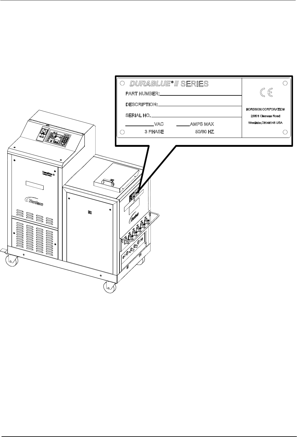
Melter Identification
You will need the model and part number of your melter when requesting
service or ordering spare parts and optional equipment. The model and part
number are indicated on the equipment identification plate that is located on
the front of the melter.
Figure 2‐6 Location of the melter identification plate