DuraBlue II Customer Product Manual.pdf - 第33页
Installation 3-5 Part 1126931_01 2018 Nordson Corporation Other Considerations Consider the following additional factors when evaluating where to install the melter. The maximum distance between the melter and each a…
Installation
3-4
Part 1126931_01
2018 Nordson Corporation
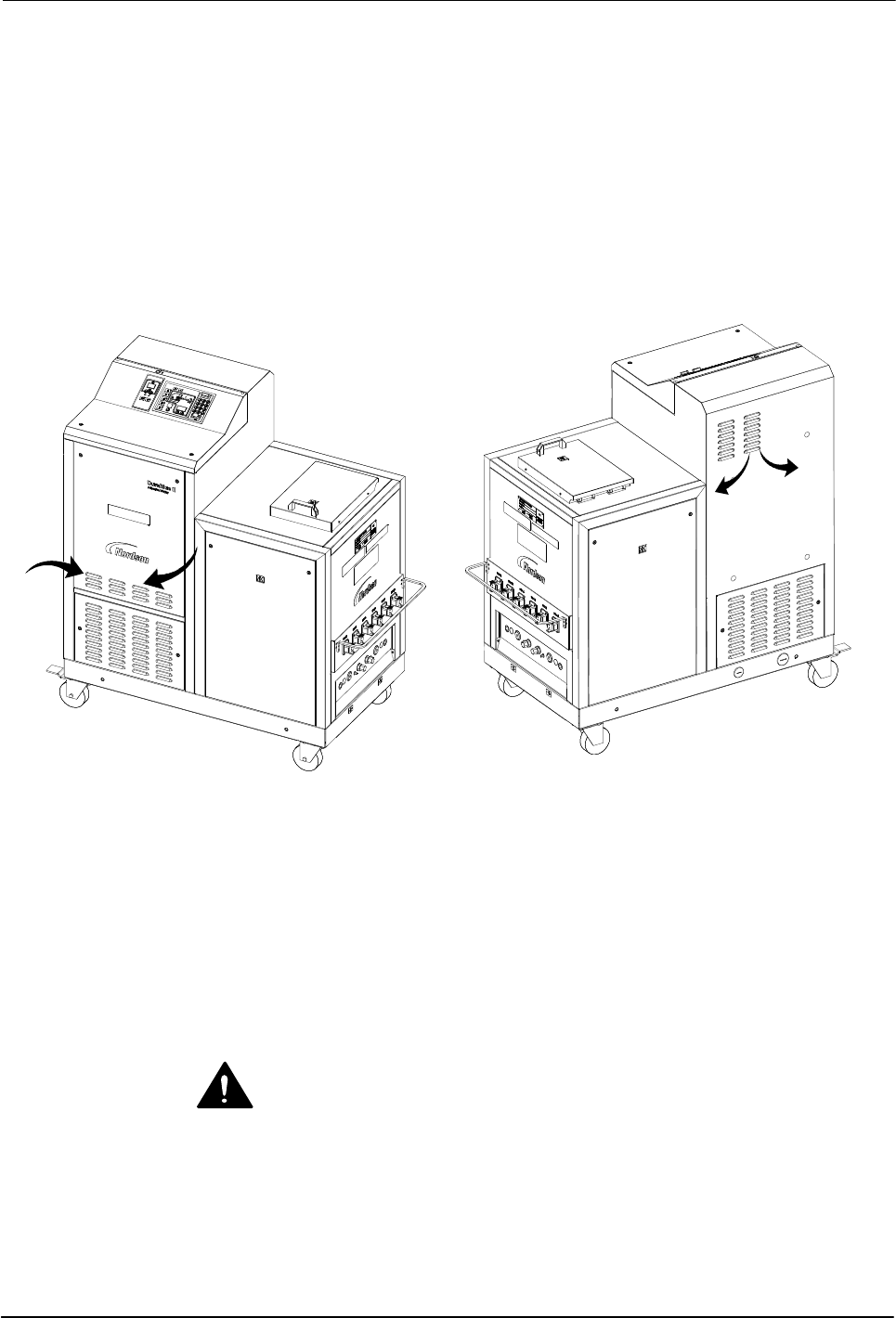
Ventilation
DuraBlue II melters are cooled by forced air. Air is drawn in through by the
ventilation fan and is exhausted out of the ventilation slots at the top of the
melter.
CAUTION! Do not block the fan air intake openings or the exhaust ventilation
slots.
Figure 3‐2 Location of the ventilation openings
Electrical Power
Before installing the melter, ensure that the melter will not be overloaded and
that the plant's electrical service is rated to handle the power required by the
melter and the hoses and applicators that you plan to use.
Refer to Appendix A, Calculating Melter Power Requirements, for information
about how to calculate the maximum allowable hose lengths and applicator
wattages that can be used in your manufacturing application.
WARNING! Risk of electrocution! Install a lockable power disconnect switch
between the electrical service and the melter. Failure to install or properly
use the disconnect switch when servicing the melter can result in personal
injury, including death.

Installation
3-5
Part 1126931_01
2018 Nordson Corporation
Other Considerations
Consider the following additional factors when evaluating where to install the
melter.
The maximum distance between the melter and each applicator is
dictated by the power requirement of each hose. Refer to Appendix A,
Calculating Melter Power Requirements, for information about how to
determine the maximum allowable length.
The operator must be able to safely reach the control panel and
accurately monitor the control panel indicators.
The operator must be able to safely observe the level of hot melt inside
the tank.
The melter must be installed away from areas with strong drafts or where
sudden temperature changes occur.
The melter must be installed where it will be in conformance with the
ventilation requirements specified in the Safety Data Sheet for the hot
melt being used.
The melter should not be exposed to excessive vibration.

Installation
3-6
Part 1126931_01
2018 Nordson Corporation
Unpacking the Melter
Before starting the installation, remove the melter from the pallet, locate the
installation kit, and inspect the melter for damaged and missing parts. Report
any problems to your Nordson representative.
Moving the Unpacked Melter
When moving the melter, always support the melter by placing any lifting
device under the chassis.
Contents of the Installation Kit
The installation kit contains a package of safety label overlays that are
printed in variety of languages. If required by local regulations, the
appropriate language overlay should be applied over the English version of
the same label. Refer to Safety Labels and Tags in Section 1, Safety, for the
location of each safety label.
Customer‐Supplied Materials
The following additional materials are also required to install the melter.
A power cable. Rigid or flexible electrical conduit will be required.
(Optional) Gear‐to‐line input signal wiring
(Optional) Input/output signal wiring