DuraBlue II Customer Product Manual.pdf - 第35页
Installation 3-7 Part 1126931_01 2018 Nordson Corporation Configuring the Electrical Service DuraBlue II melters are shipped from the factory without an attached power cable. To configure the melter to function in your…

Installation
3-6
Part 1126931_01
2018 Nordson Corporation
Unpacking the Melter
Before starting the installation, remove the melter from the pallet, locate the
installation kit, and inspect the melter for damaged and missing parts. Report
any problems to your Nordson representative.
Moving the Unpacked Melter
When moving the melter, always support the melter by placing any lifting
device under the chassis.
Contents of the Installation Kit
The installation kit contains a package of safety label overlays that are
printed in variety of languages. If required by local regulations, the
appropriate language overlay should be applied over the English version of
the same label. Refer to Safety Labels and Tags in Section 1, Safety, for the
location of each safety label.
Customer‐Supplied Materials
The following additional materials are also required to install the melter.
A power cable. Rigid or flexible electrical conduit will be required.
(Optional) Gear‐to‐line input signal wiring
(Optional) Input/output signal wiring
Installation
3-7
Part 1126931_01
2018 Nordson Corporation
Configuring the Electrical Service
DuraBlue II melters are shipped from the factory without an attached power
cable. To configure the melter to function in your facility, you must connect a
properly rated power cable.
The maximum power draw of the melter for any supported service code is
86 A.
Residual Current Circuit Breakers
Local regulations in some geographic areas or industrial branches may
require residual current circuit breakers.
Then observe the following points:
Permanent installation is required (fixed line voltage connection)
The residual current circuit breaker is to be installed only between the
power supply and the melter.
Only residual current circuit breakers sensitive to pulsating current or
universal current (> 30 mA) may be used.
Connecting the Electrical Service
NOTE: The melter must be installed securely (permanent power supply
connection).
WARNING! Operate only at the operating voltage shown on the ID plate.
NOTE: Permitted deviation from the rated line voltage is 10%.
NOTE: The power cable cross‐section must comply with the maximum
power consumption (refer to Section 8, Technical Data).
WARNING! Ensure that cables do not touch rotating and/or hot melter
components. Do not pinch cables and check regularly for damage. Replace
damaged cables immediately!
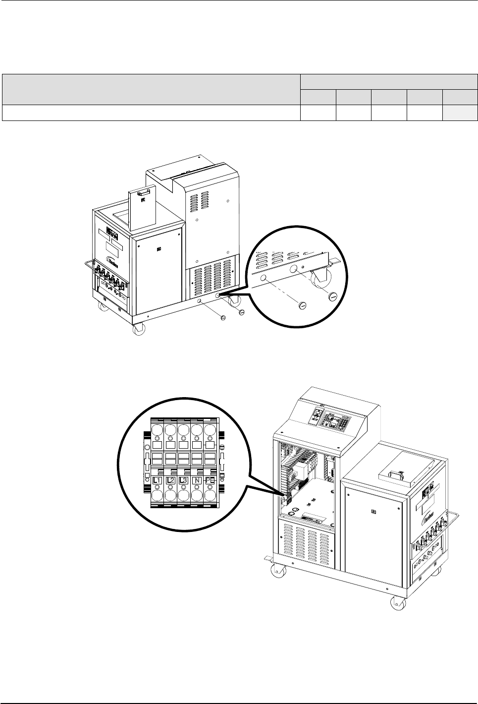
1. See Figure 3‐3. Route the power cable into the electrical cabinet through
the strain relief on the side of the base.
NOTE: Do not route any input/output wiring through this strain relief.
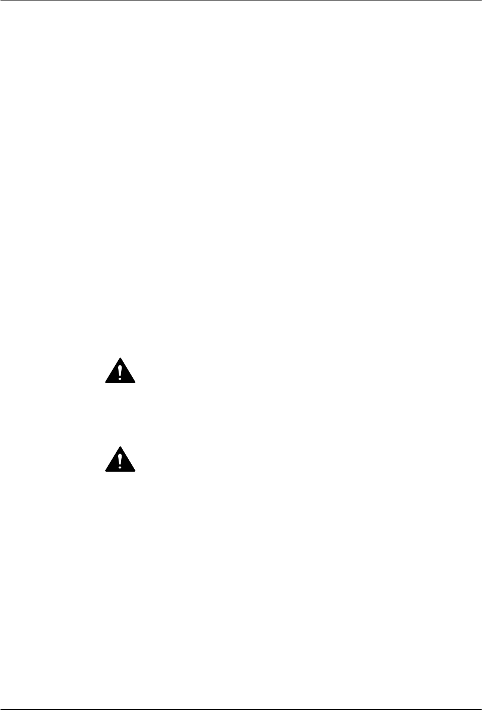
2. Connect the power cable to the service terminal block as indicated in
table Table 3‐1 and illustrated in Figure 3‐3.
3. Connect the service ground lead to the ground terminal located on the
DIN rail at XL0:PE.