DuraBlue II Customer Product Manual.pdf - 第42页
Installation 3-14 Part 1126931_01 2018 Nordson Corporation Quick Setup (contd) Table 3‐2 Common Operating Parameters Parameter Parameter Name Purpose Default Value 4 Ready Delay Time A timer that delays the activation …

Installation
3-13
Part 1126931_01
2018 Nordson Corporation
Setting Up the Melter
After physically installing the melter, it must be set up to support your
manufacturing process. Melter setup consists of enabling or making changes
to factory‐set operating parameters that affect the use and function of the
melter. The operating temperature (set‐point) of the tank and each hose and
applicator is also established during melter setup.
The melter is shipped from the factory with the most commonly used
operating parameters already set up. The factory setup can be modified at
any time to suit your manufacturing process.
Quick Setup
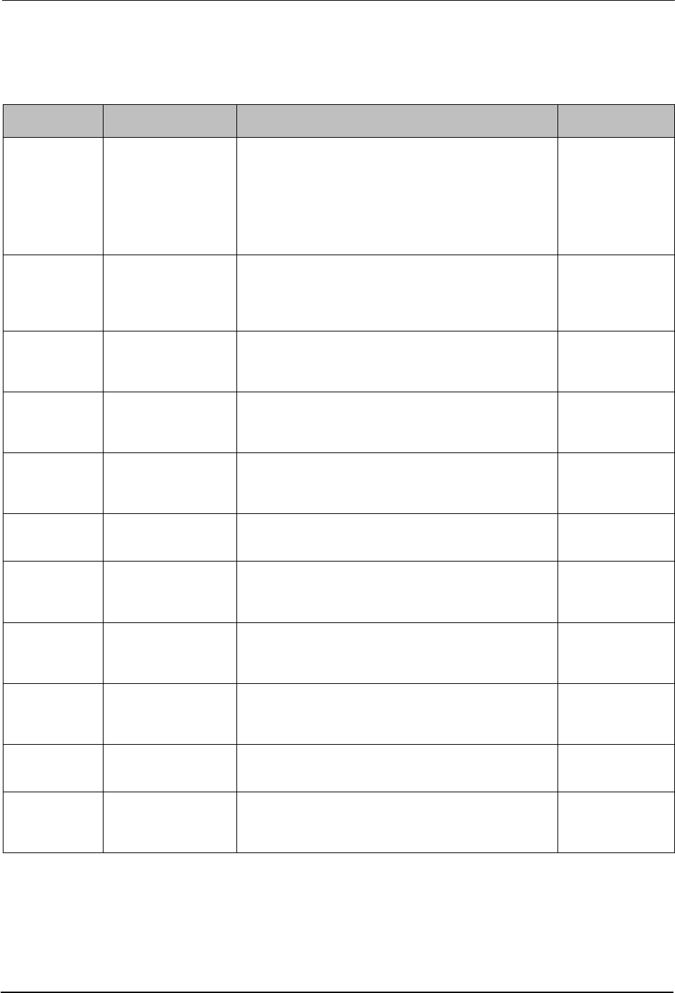
Table 3‐2 describes the most commonly used operating parameters and their
factory settings. Review the table to determine if the factory settings for each
parameter will support your manufacturing process. If the default values for
each of these operating parameters are appropriate for your manufacturing
process, then no melter setup is required. Go directly to Set‐point
Temperature of the Tank, Hoses, and Applicators later in this section to
complete the installation process.
If you need to make changes to the factory setup or if you want to learn about
other operating parameters, go to the next part in this section, Operating
Parameters.
Installation
3-14
Part 1126931_01
2018 Nordson Corporation
Quick Setup (contd)
Table 3‐2 Common Operating Parameters
Parameter Parameter Name Purpose Default Value
4 Ready Delay Time
A timer that delays the activation of the ready LED for
a pre‐defined time period after the tank, hoses, and
applicators are at the desired set‐point temperature.
The ready delay timer will only activate if the
temperature of the tank, at the time the melter is turned
on, is below its assigned set‐point temperature by
27 C (50 F) or more.
0 minutes
5
Service Interval
Time
A timer that turns on a service LED when the value set
for the timer equals the number of hours that the
heaters have been on. The service LED is used to
signal the need for maintenance.
500 hours
7 Motor Off Delay
If the switch receptacle is used, this parameter
determines the amount of time the motor will remain
on after the switched device is turned off.
0 seconds
8 Automatic Pump On
Allows the pump to start automatically when system
ready is reached, provided that the pump has been
enabled by pressing the pump key.
Enabled
11 Create Password
Sets a password that must be entered before any
melter operating parameter or set‐point temperature
can be changed.
5000
20 Temperature Units
Sets the units of the temperature display to degrees
Celsius(C) or to degrees Fahrenheit (F).
C
21
Over Temperature
Delta
Sets the number of degrees that any heated
component can exceed its assigned set‐point
temperature before an over temperature fault occurs.
15 C (25 F)
22
Under Temperature
Delta
Sets the number of degrees that any heated
component can drop below its assigned set‐point
temperature before an under temperature fault occurs.
25 C (50 F)
23 Standby Delta
Sets the number of degrees that the temperature of all
heated components will be decreased when the melter
is placed into the standby mode.
50 C (100F)
26
Manual Standby
Time
Sets the amount of time the melter will remain in the
standby mode after the standby key is pressed.
Disabled
50 to 77 Seven‐day Clock
A group of parameters that control the melter's clock.
The clock is used to automatically turn the heaters on
and off and to place the melter into the standby mode.
Disabled
Installation
3-15
Part 1126931_01
2018 Nordson Corporation
Operating Parameters
The melter uses operating parameters to store non‐editable and editable
values. Non‐editable values are those that provide information about the
historical performance of the melter. Editable values are either a numeric
set‐point or a control option setting. Control options settings affect the display
of information or the function of the melter.
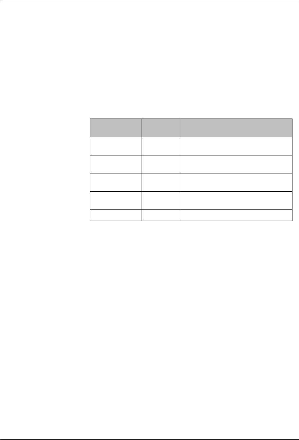
Operating parameters are stored in the melter's firmware in the form of a
sequentially numbered list. The list is organized into the logical groups
described in Table 3‐3.
Table 3‐3 Parameter Groups
Group
Parameter
Numbers
Group Description
Standard
0 to 8 and
10-14
Noneditable and other frequently used
parameters
Temperature
Control
20 to 29 Control heaters
Input Setup 30 to 39
Configure the standard and optional
inputs
Output Setup 40 to 46
Configure the standard and optional
outputs
Seven‐day Clock 50 to 77 Configure the clock feature
In addition to the ability to read and edit parameter values, you can also save
and restore the current value of every operating parameter and review a log
of the last ten changes that were made to editable parameters.
Selecting Operating Parameters
Table 3‐4 provides a complete list of the operating parameters. Review the
list to determine which operating parameters would best support your
manufacturing process. Refer to Appendix B, Operating Parameters, for
detailed information about each parameter. Appendix B contains a complete
description of each parameter, including its affect on the melter, default
value, and format.
NOTE: Parameters that are used to configure optional equipment or that are
otherwise reserved in the firmware are excluded from Table 3‐4 and
Appendix B.