DuraBlue II Customer Product Manual.pdf - 第45页
Installation 3-17 Part 1126931_01 2018 Nordson Corporation If the numeric set‐point or control option is not accepted, the right display will indicate dashes (‐‐‐‐) for three seconds and then it will change back to t…
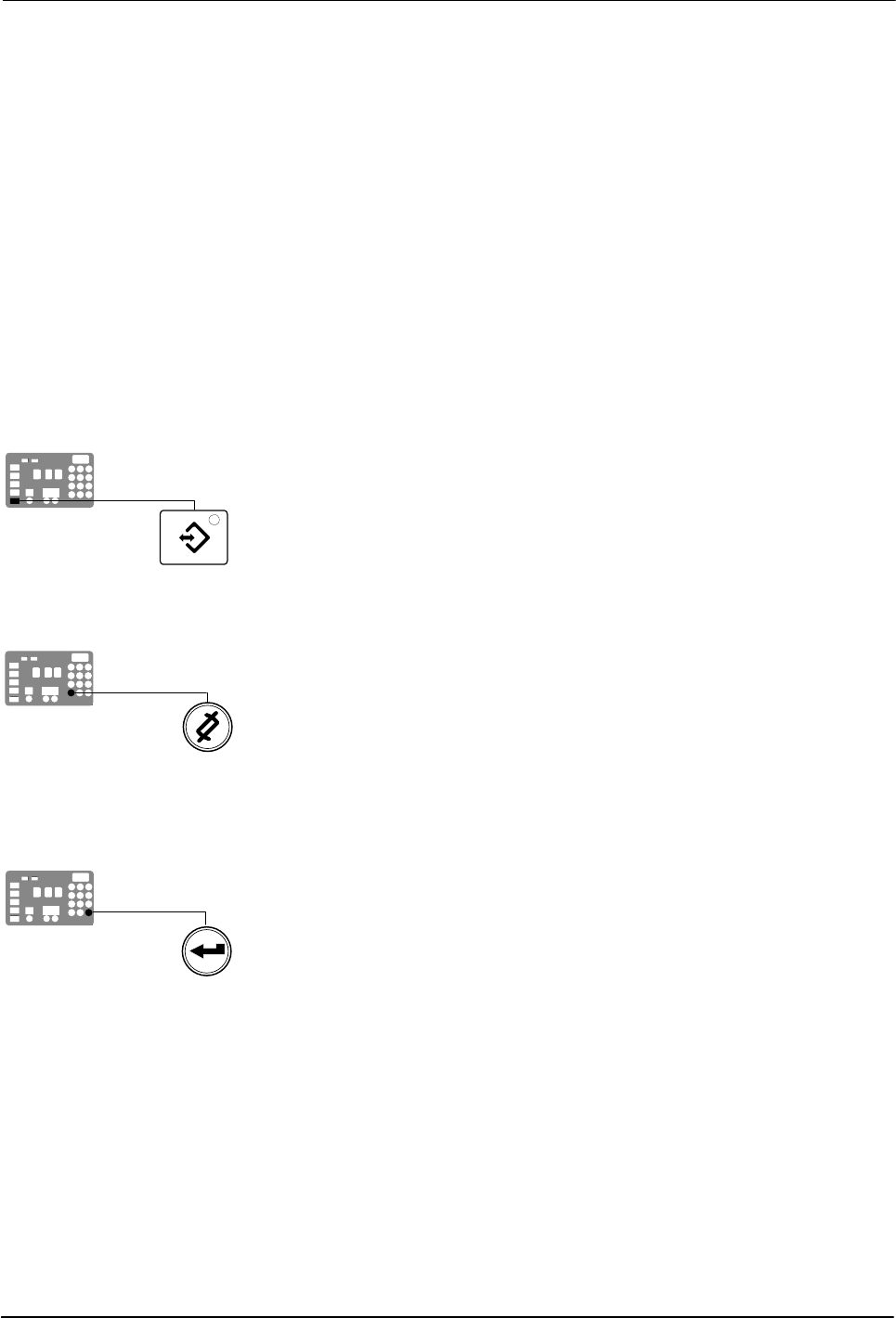
Setup key
Clear/Reset key
Enter key
Installation
3-16
Part 1126931_01
2018 Nordson Corporation
Reading or Editing Operating Parameters
Regardless of whether a parameter's value is editable or not, the procedure
for accessing each parameter in order to read or edit its current value is the
same.
To read or edit a parameter
1. Place the main power and control switches on the ON position.
The melter performs a start‐up check.
2. Press the Setup key.
The left display flashes parameter 1.
3. Use the numeric keypad to enter the number of the desired parameter.
Refer to Table 3‐4 for a complete list of parameters.
NOTE: If you incorrectly enter the parameter number, press the
Clear/Reset key to return to parameter 1 and then re‐enter the correct
parameter number.
When you have finished entering the one‐ or two‐digit parameter number,
the right display indicates the parameter's current value.
4. Do one of the following:
If the value is noneditable, refer to Monitoring the Melter in Section4,
Operation.
If the value is editable go to step 5.
5. Press the Enter key.
The right display flashes.
6. Use the keypad to enter the desired numeric set‐point or control option
into the right display. Refer to Appendix B, Operating Parameters, for
information about the numeric value or control option choices for each
parameter.
NOTE: If the keypad has no affect on the right display, the melter is
password protected. You must enter a valid password before you can
edit parameters. Refer to Entering a Password in Section 4, Operation.
7. Press the Enter key.
The melter checks that the new value or control option is acceptable.
If the numeric set‐point or control option is accepted, the left and right
displays index to the next sequential parameter number and value.
Installation
3-17
Part 1126931_01
2018 Nordson Corporation
If the numeric set‐point or control option is not accepted, the right
display will indicate dashes (‐‐‐‐) for three seconds and then it will
change back to the original value.
8. Repeat step 5 through step 7 to read or change the next sequential
parameter number or press the Setup key to exit the setup mode.
Table 3‐4 Operating Parameters
Parameter Name Range of Values Default Value
Standard
0 Enter Password 0 to 9999 4000
1 Total Hours with Heaters On
(noneditable)
0 to 9999 0
2 Fault Log (noneditable) — _‐F0 (empty)
3 Change History Log (noneditable) — P‐_ (empty)
4 Ready Delay Time 0 to 60 minutes 0 minutes
5 Service Interval Time 0 to 8736 hours 500 hours
6 Service LED Heater Hours 0 to 9999hours 0
8
1
Automatic Pump On 0 (disabled) or 1(enabled) 1 (enabled)
10 Enable or Disable Password 0 (disabled) or 1(enabled) 0 (disabled)
11 Create Password 0 to 9999 5000
12
1
Change Hose 1 Output to Electric
Applicator Activation
0 (disabled) or 1 (enabled) 0 (disabled)
13
1
Change Hose 2 Output to Electric
Applicator Activation
0 (disabled) or 1 (enabled) 0 (disabled)
14 External Communications Lock‐out 0 or 1 0 (disabled)
Temperature Control
20 Temperature Units (degrees C or F) C (degrees Celsius) or F
(degrees Fahrenheit)
C (degrees Celsius)
21 Over Temperature Delta 5 C (10 F) to 60C(110 F) 15 C (25 F)
22 Under Temperature Delta 5 C (10 F) to 60C(110 F) 25 C (50 F)
23 Standby Delta 25 C (50 F) to 190C (350 F) 50 C (100 F)
24 Automatic Standby Timeout 0 to 1440minutes 0 (disabled)
25 Automatic Heaters Off Time 0 to 1440minutes 0 (disabled)
26 Manual Standby Time 0 to 180 minutes 0 (disabled)
27 Hose Standby Delta 1 C (1 F) to 190C (350 F) 0 (disabled)
28 Applicator Standby Delta 1 C (1 F) to 190C (350 F) 0 (disabled)
29 Internal Zone Temperate Offset 0 C (0 F) to ‐15C (‐30 F) 0 (disabled)
30 Standard Input 1
0–8 and 10-14
10 (Automatic
Standby)
31 Standard Input 2 0–8 and 10-14 1 (Standby on/off)
32 Standard Input 3 0–8 and 10-14 2 (Heaters on/off)
33 Standard Input 4
0–8 and 10-14
4 (Hose/applicator 1
enable/disable)
34 Optional Input 5 0–8 and 10-14 0 (disabled)
1
Not used with DuraBlue II melters.
Installation
3-18
Part 1126931_01
2018 Nordson Corporation
To read or edit a parameter (contd)
Parameter Name Range of Values Default Value
Input Setup
35 Optional Input 6 0–8 and 10-14 0 (disabled)
36 Optional Input 7 0–8 and 10-14 0 (disabled)
37 Optional Input 8 0–8 and 10-14 0 (disabled)
38 Optional Input 9 0–8 and 10-14 0 (disabled)
39 Optional Input 10 0–8 and 10-14 0 (disabled)
Output Setup
40 Standard Output 1 0–6 1 (Ready)
41 Standard Output 2 0–6 3 (Fault)
42 Standard Output 3 0–6 4 (Not used)
43 Optional Output 4 0–6 0 (disabled)
44 Optional Output 5 0–6 0 (disabled)
45 Optional Output 6 0–6 0 (disabled)
46 Optional Output 7 0–6 0 (disabled)
Seven‐day Clock
50 Current Day 1 to 7 (1 = Monday) —
51 Current Hour 0000 to 2359 —
55 Schedule 1 Heaters On 0000 to 2359 06:00
56 Schedule 1 Heaters Off 0000 to 2359 17:00
57 Schedule 1 Enter Standby 0000 to 2359 —:—
58 Schedule 1 Exit Standby 0000 to 2359 —:—
60 Schedule 2 Heaters On 0000 to 2359 —:—
61 Schedule 2 Heaters Off 0000 to 2359 —:—
62 Schedule 2 Enter Standby 0000 to 2359 —:—
63 Schedule 2 Exit Standby 0000 to 2359 —:—
65 Schedule 3 Heaters On 0000 to 2359 —:—
66 Schedule 3 Heaters Off 0000 to 2359 —:—
67 Schedule 3 Enter Standby 0000 to 2359 —:—
68 Schedule 3 Exit Standby 0000 to 2359 —:—
Continued…