DuraBlue II Customer Product Manual.pdf - 第48页
Installation 3-20 Part 1126931_01 2018 Nordson Corporation Set‐point Temperature of the Tank, Hoses, and Applicators The melter is shipped from the factory with the tank set‐point temperature at 175 C (350 F) and t…
Installation
3-19
Part 1126931_01
2018 Nordson Corporation
Parameter Name Range of Values Default Value
71 Schedule for Monday 0-7 0
72 Schedule for Tuesday 0-7 0
73 Schedule for Wednesday 0-7 0
74 Schedule for Thursday 0-7 0
75 Schedule for Friday 0-7 0
76 Schedule for Saturday 0-7 0
77 Schedule for Sunday 0-7 0
You can exit the setup mode at any time by
pressing the Setup key.
Parameter numbers that are not applicable are
skipped when you scroll through the operating
parameter list in the left display.
When the right display is flashing, you can
quickly set the value of the current parameter
to its lowest possible value by simultaneously
pressing both of the right‐display scroll keys.
While in the setup mode, if no key is pressed
for two minutes, the melter will return to the
automatic scan mode.
You can also use the right‐display scroll keys
to enter or change a parameter's value or
control option. After entering the parameter's
number in the left display, press either of the
right‐display scroll keys to change the value or
control option.
Using a personal computer that is connected
to the melter through the serial port, you can
view and change all of the operating
parameters from a single computer screen.
Refer to Appendix C, Melter
Communications
If password protection is enabled, the melter
will return to the password protected mode
whenever you exit the setup mode.
Appendix B, Parameter 10

Installation
3-20
Part 1126931_01
2018 Nordson Corporation
Set‐point Temperature of the Tank, Hoses, and Applicators
The melter is shipped from the factory with the tank set‐point temperature at
175 C (350 F) and the hose and applicator set‐point temperatures at 0
degrees (turned off).
Before the melter can be used, a set‐point temperature must be assigned to
the tank, hoses, and applicators. Assign set‐point temperatures using any of
the following methods:
Global—The tank and all hoses and applicators are set to the same
set‐point temperature.
Global‐by‐component group—All of the hoses or all of the applicators
are set to the same set‐point temperature.
Individual Component—The set‐point temperature of the tank and each
hose and applicator is set individually.
Since most manufacturing processes will require the tank, hoses, and
applicators to be set to the same temperature, only the global method of
assigning set‐point temperatures is described in this section. For information
about the other two methods of assigning set‐point temperatures, refer to
Adjusting Component Temperatures in Section 4, Operation.
As with operating parameters, you can also save and restore set‐point
temperatures and review past changes that were made to set‐point
temperatures.
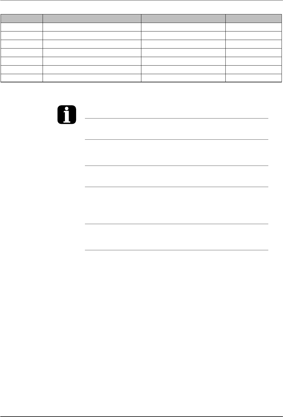
Tank key
Left display and
scroll key
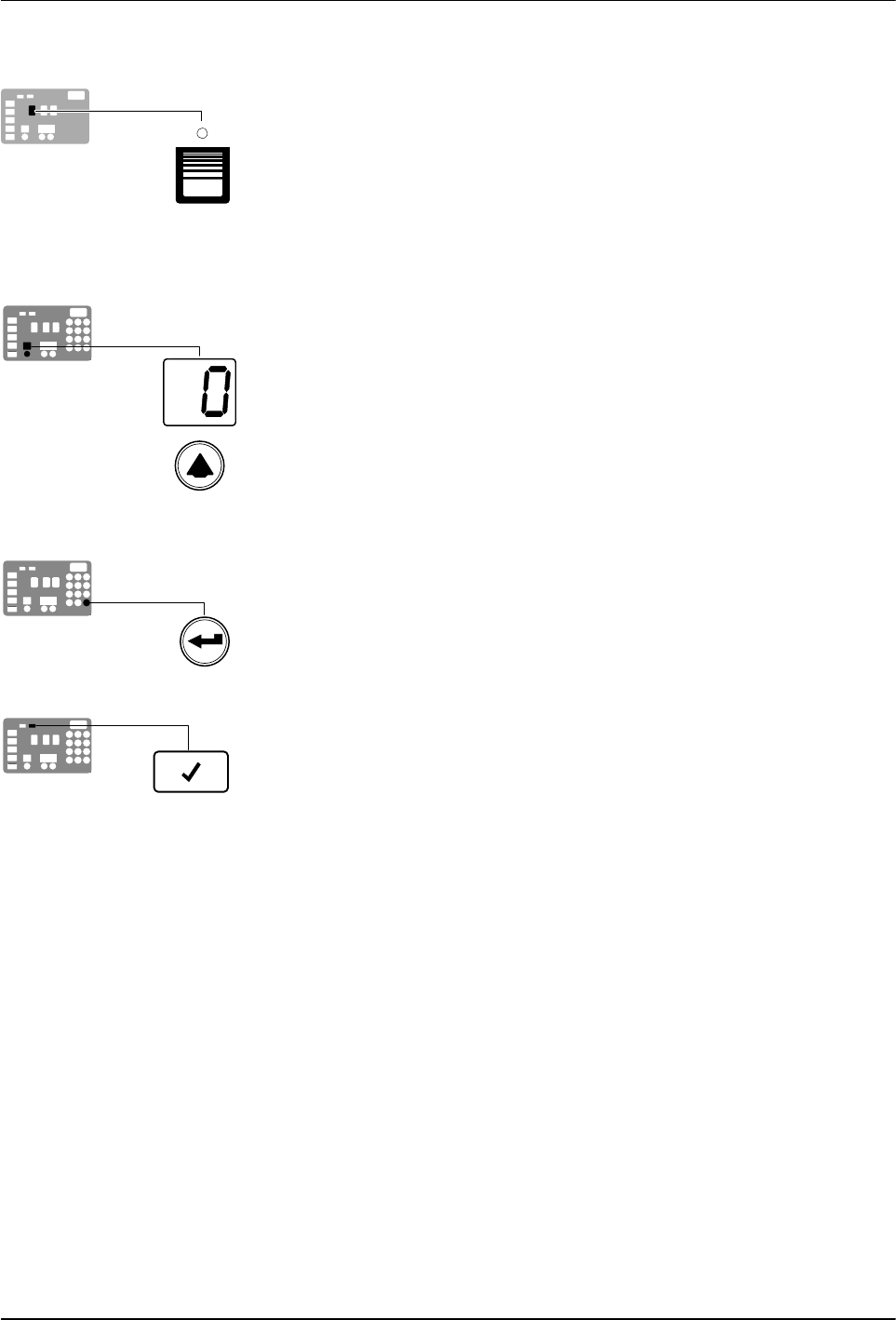
Enter key
Ready LED
Installation
3-21
Part 1126931_01
2018 Nordson Corporation
To assign a global set‐point temperature
1. Press and hold the Tank key for three seconds.
The left display flashes 1.
2. Scroll the left display to 0.
The right display indicates all dashes (‐‐‐‐) and the LEDs on the tank,
hose, and applicator keys turn green.
3. Press the Enter key.
The right display flashes.
4. Use the numeric keypad to enter the set‐point temperature
recommended by the manufacturer of the hot melt.
Refer to the technical data sheet provided by the manufacturer of the hot
melt to determine the optimal set‐point temperature.
5. Press the Tank key.
Each component begins to heat or cool to the new global set‐point
temperature and the melter returns to the automatic scan mode.
When all of the components reach the global set‐point temperature, the
ready LED turns on (green).