DuraBlue II Customer Product Manual.pdf - 第53页
Installation 3-25 Part 1126931_01 2018 Nordson Corporation Unused log entries in the change history log are indicated by “P‐_” in the right display. To view how many heater hours have elapsed since a specific change (d…
Installation
3-24
Part 1126931_01
2018 Nordson Corporation
Review Parameter and Set‐point Temperature Changes (contd)
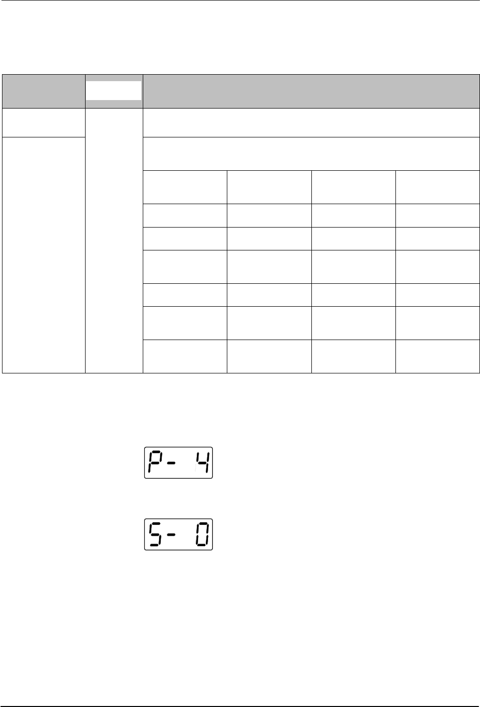
Table 3‐5 Change History Log
First Digit
Second
Digit
Third and Fourth Digits
P (Parameter)
-
Indicates the number of the parameter that was changed
S (Set‐point)
Are used in conjunction with the LEDs on the component keys to indicate the
location and method of a set‐point temperature change.
When this LED is
on..
And the Fourth
Digit Indicates..
The change was
to..
And the Method
of Change was..
Tank Key 1 The tank Individual
Hose Key 1– 6 A single hose Individual
Applicator Key 1– 6
A single
applicator
Individual
All Keys 0 All components Global
Hose Key 0 All hoses
Global‐by‐
component
Applicator Key 0 All applicators
Global‐by‐
component
Change History Log Examples
Example 1:
Parameter 4 (ready delay) was changed.
Example 2:
If the LED on the applicator key is on, then this display would
indicate that the global‐by‐component method was used to change the
temperature of the applicators.
Installation
3-25
Part 1126931_01
2018 Nordson Corporation
Unused log entries in the change history log are
indicated by “P‐_” in the right display.
To view how many heater hours have elapsed
since a specific change (displayed) was made,
simultaneously press both of the right‐display
scroll keys.
Setting Up Inputs/Outputs
DuraBlue II adhesive melters are equipped with four standard inputs. Each
input is customer‐wired to the melter and then set up to provide one of the
following control options:
Place the melter into the standby mode
Turn the heaters on and off
Enable or disable a specific hose or applicator
Enable the motor
The input contacts use a constant 10 to 30 VDC signal voltage. The inputs
are not polarity sensitive.
WARNING! The operator can override the melter inputs by using the control
panel function keys. Ensure that the control logic for any external device that
sends an input signal to the melter is programmed to prevent the creation of
an unsafe condition in the event that the operator overrides an external input
to the melter.
The melter is also equipped with three user‐configurable outputs. Outputs
are used to communicate with user‐supplied production equipment or control
hardware, such as a programmable logic controller.
Each output is customer‐wired and then set up in the melter's firmware to
provide one of the following outputs:
The melter is ready
The melter is ready and the motor is enabled
A fault has occurred
The hot melt level is low (only if the optional level switch is installed)
The service LED is on
All outputs contacts are rated at 240 VAC 2 A or 30 VDC 2 A. All contacts are
normally open when the melter is turned off.
Installation
3-26
Part 1126931_01
2018 Nordson Corporation
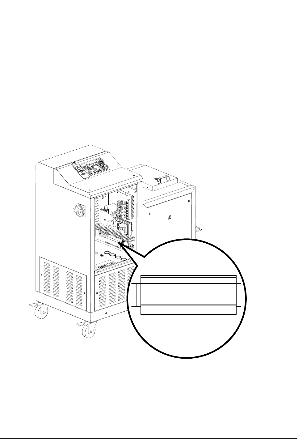
Wire Inputs/Outputs to the Melter
See Figure 3‐6.
1. Route a 2‐, 4, 6, or 8‐conductor signal cable from the control equipment
to the melter and through the PG‐16 penetration on side of the base. Use
rigid or flexible conduit or a suitable strain relief to protect the cable from
the sharp edge of the conduit penetration.
NOTE: Use a signal cable suitable for NEC class1 remote control and
signaling circuits. To reduce the possibility of electrical shorting, route the
cable so that it does not touch nearby circuit boards.
2. Connect each pair of input and output wires to the appropriate terminals
on terminal block XI. Refer to Table 3‐6 for the terminal numbers that
correspond to each input.
Figure 3‐6 Location of the XI terminal block for connecting input/output wiring