DuraBlue II Customer Product Manual.pdf - 第55页
Installation 3-27 Part 1126931_01 2018 Nordson Corporation Set Up Inputs/Outputs Set up the parameter control option for each input and output that you connected to the melter. Table 3‐6 lists the available control opt…
Installation
3-26
Part 1126931_01
2018 Nordson Corporation
Wire Inputs/Outputs to the Melter
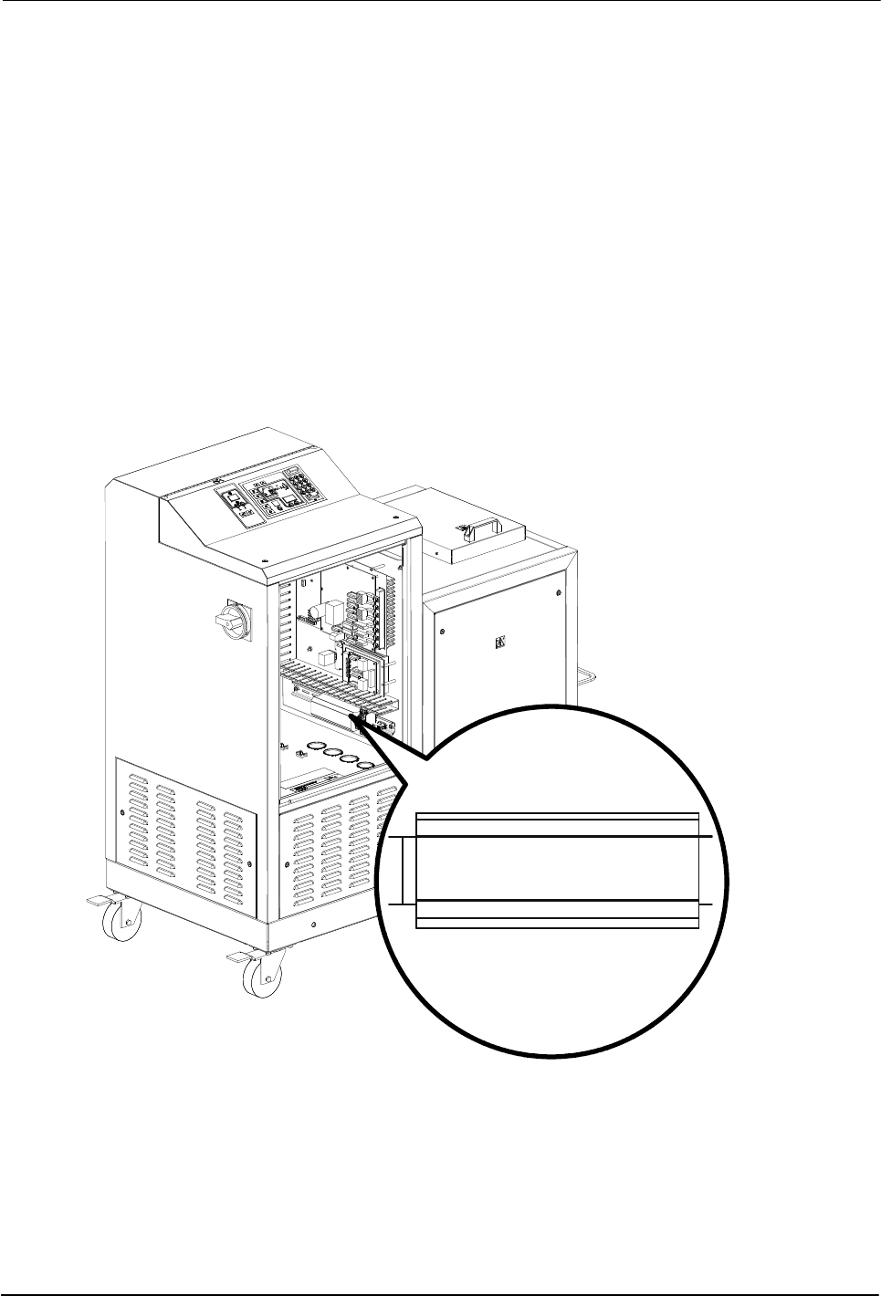
See Figure 3‐6.
1. Route a 2‐, 4, 6, or 8‐conductor signal cable from the control equipment
to the melter and through the PG‐16 penetration on side of the base. Use
rigid or flexible conduit or a suitable strain relief to protect the cable from
the sharp edge of the conduit penetration.
NOTE: Use a signal cable suitable for NEC class1 remote control and
signaling circuits. To reduce the possibility of electrical shorting, route the
cable so that it does not touch nearby circuit boards.
2. Connect each pair of input and output wires to the appropriate terminals
on terminal block XI. Refer to Table 3‐6 for the terminal numbers that
correspond to each input.
Figure 3‐6 Location of the XI terminal block for connecting input/output wiring
Installation
3-27
Part 1126931_01
2018 Nordson Corporation
Set Up Inputs/Outputs
Set up the parameter control option for each input and output that you
connected to the melter. Table 3‐6 lists the available control options. Refer to
Setting Up the Melter earlier in this section for information about how to
select operating parameters and edit parameter control options.
With the exception of the motor
enable/disable control option (Table 3‐6,
Input/Output Data), All inputs are
transition‐based.
Input Setup in Appendix B
The input capacity of the melter may be
increased from four inputs to a total of
ten inputs by adding an optional I/O
expansion card that is available from
Nordson Corporation.
Section 7, Parts
The output capacity of the melter may
be increased from three outputs to
seven outputs by adding an optional I/O
expansion card that is available from
Nordson Corporation.
Section 7, Parts
Table 3‐6 Input/Output Data
Item Description
Operating
Parameter
Control Options Terminals Notes
1 Standard input 1 30 0 - Input Disabled
1 - Standby On/Off
2 - Heaters On/Off
3 - Motor 1 Enable/Disable
4 - Hose/Applicator 1
Enable/Disable
5 - Hose/Applicator 2
Enable/Disable
6 - Hose/Applicator 3
Enable/Disable
7 - Hose/Applicator 4
Enable/Disable
8 - Hose/Applicator 5
Enable/Disable
9 - Hose/Applicator 6
Enable/Disable
10 – Automatic standby (Default)
11 - Motor 2 Enable/Disable
XI:1, XI:2 A, B
C
D
C
Continued...

Installation
3-28
Part 1126931_01
2018 Nordson Corporation
Set Up Inputs/Outputs (contd)
Item Description
Operating
Parameter
Control Options Terminals Notes
2 Standard input 2 31 0 - Input Disabled
1 - Standby On/Off (Default)
2 - Heaters On/Off
3 - Motor 1 Enable/Disable
4 - Hose/Applicator 1
Enable/Disable
5 - Hose/Applicator 2
Enable/Disable
6 - Hose/Applicator 3
Enable/Disable
7 - Hose/Applicator 4
Enable/Disable
8 - Hose/Applicator 5
Enable/Disable
9 - Hose/Applicator 6
Enable/Disable
11 - Motor 2 Enable/Disable
XI:3, XI:4
C
C
3 Standard input 3 32 Same as parameter 31
(Default=2)
XI:5, XI:6
4 Standard input 4 33 Same as parameter 31
(Default=4)
XI:7, XI:8
5 Standard output 1 40 0 - Output Disabled XI:9, XI:10 F
1 - Ready (Default) F
2 - Ready and the Motor is On F
3 - Fault G
4 - Tank Low Level
5 - Service LED is On
6 - Alert H
NOTE A: Parameter 30 has 12 control options. parameters 31, 32, and 33 each have only 11 control options.
B: Parameters 34 through 39 are reserved for the six inputs created when the optional I/O expansion card is installed. The
six optional inputs have the same control options as parameter 31.
C: Parameters are disabled in DuraBlue II adhesive melters. Refer to parameters 9-12 in this table.
D: If control option 10 is selected for input 1, a time must be set in parameter 24.
E: Refer to the instruction sheet provided with the optional I/O expansion card for wiring information.
F: When control option condition occurs, contacts close. Contacts are normally open when power is off.
G: When control option condition occurs, contacts open. Contacts are normally open when power is off.
H: Control option 6 provides an output signal when a potential fault is detected. If control option 3 and 6 are both used, then
both a fault output and an alert output signal will be present when the fault LED turns on.
I: For wiring information, refer to the instruction sheet that is provided with the optional I/O expansion card
Continued...