DuraBlue II Customer Product Manual.pdf - 第61页
DuraBlue‐II service kit motor drive keypad PAR 430 Analog Input 1 REM AUTO SET 8 Installation 3-33 Part 1126931_01 2018 Nordson Corporation Programming This parameter comes pre‐set at the factory. Use the service kit m…
Installation
3-32
Part 1126931_01
2018 Nordson Corporation
Setting Up Motor Run Status Monitoring
If desired, you can set up the melter to allow remote monitoring of the run
status (running or not running) of the pump motors.
Wiring
To use the motor run status monitoring capability, connect wiring from the
parent machine to the appropriate terminals on terminal block XI inside the
electrical enclosure. See Figure 3‐6 for the location of terminal block XI.
Refer to Table 3‐6 for the terminal numbers that correspond to each
input/output.
NOTE: The relay contact between terminals XI:25/XI:26 and XI:27/XI:28 is
normally open. When the motor is running, these contacts should close.
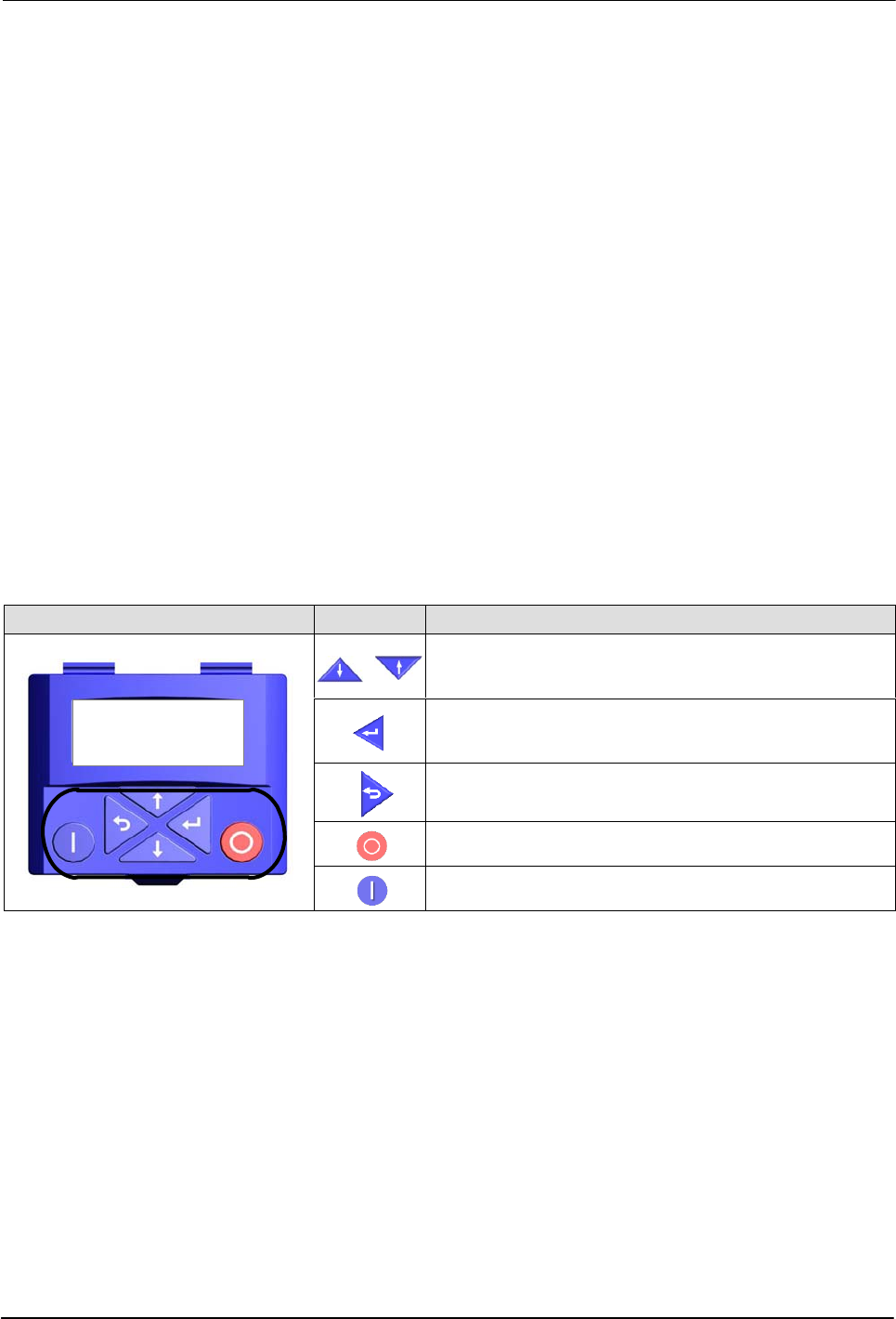
Keypad Buttons
The motor driver keypad is not shipped with the melter, in order to use the
keypad you will need to order the keypad service kit (P/N 7411739)
separately.
An explanation of the keypad button functions is given in the following table.
Keypad Buttons Description
PAR 430
Analog Input 1
REM AUTO SET
8
Menu navigation (UP/Down).
Adjust parameter values.
Enter (sub-) menu/parameter.
Confirm parameter.
Exit (sub-) menu/parameter.
Stop inverter
Release inverter
DuraBlue‐II service kit motor drive
keypad
PAR 430
Analog Input 1
REM AUTO SET
8
Installation
3-33
Part 1126931_01
2018 Nordson Corporation
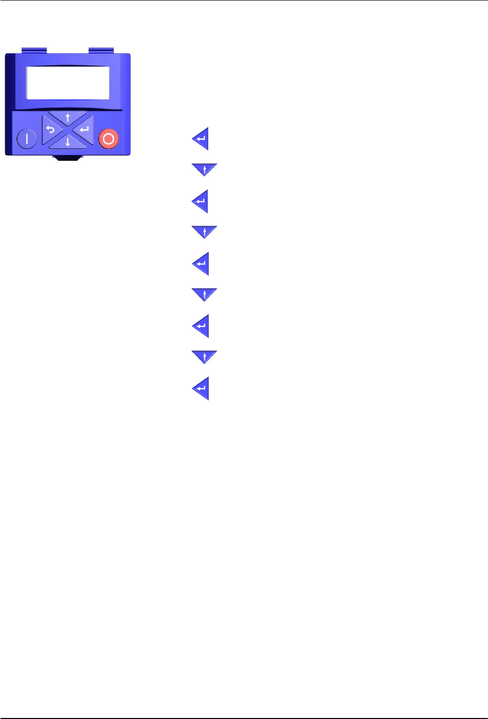
Programming
This parameter comes pre‐set at the factory.
Use the service kit motor drive keypad, PN 7411739 to set up the motor run
status monitoring for each motor. Refer to Changing a Motor Drive Parameter
in Section 6, Troubleshooting, for a detailed procedure for changing a motor
drive parameter.
1. Press
(ENT) until the Group Screen is displayed.
2. Press
(UP) until Group 4 is displayed.
3. Press
(ENT) to access I/O parameters.
4. Press
(UP) to select the parameter until “P420.00” is displayed.
5. Press
(ENT) to select the sub parameter.
6. Press
(UP) to select P420.01.
7. Press
(ENT) to set parameter.
8. Press
(UP) to change parameter until 51 is displayed.
9. Press
(ENT) >3S to save parameters to memory.

Installation
3-34
Part 1126931_01
2018 Nordson Corporation
Installing Optional Equipment
Each item of optional equipment is shipped with instructions for installing and
operating the equipment. Refer to Section 7, Parts, for equipment part
numbers.
Connecting an Applicator Driver, Pattern
Controller, or Timer
If applicable, complete the melter installation by connecting the applicators to
the desired applicator driver, pattern controller, or timer. Refer to the product
manual provided with the device for information about installing and
operating the equipment.
Flushing the Melter
Before using the melter for production, it should be flushed to remove any
residue left over from factory‐testing. Flushing the melter is accomplished by
processing a minimum of one tank volume of hot melt through the melter,
hoses, and applicators.
Refer to Section 4, Operation, for information about filling the tank and
operating the melter.
Disposing of Melter
When your Nordson product has reached the end of its useful life, dispose of
it in accordance with local regulations.