DuraBlue II Customer Product Manual.pdf - 第64页
Filling the tank Component keys (tank, hose, and applicator) Operation 4-2 Part 1126931_01 2018 Nordson Corporation Filling the Tank CAUTION : Before filling the tank, ensure that tank and material are clean and free o…

Operation
4-1
Part 1126931_01
2018 Nordson Corporation
Section 4
Operation
WARNING! Allow only qualified personnel to perform the following tasks.
Follow the safety instructions in this document and all other related
documentation.
This section provides information about the following operator‐level tasks:
Filling the melter tank
Starting the melter
(Optional) Adjusting the speed of the motor(s)
(Optional) Adjusting material pressure
Monitoring melter operation
Adjusting the operating temperature of heated components
Using the melter function keys
Shutting the melter down
Most of the controls described in this section are located on the
control panel. Refer to Key Components in Section 2, Introduction, for
the location of the controls and indicators described in this section.
Additional Information
This section presents operating procedures in their most commonly used
form. Procedural variations or special considerations are explained in the
additional information table that follows most procedures. Where applicable,
some table entries also contain cross‐reference information. Additional
information tables are indicated by the symbol shown to the left.
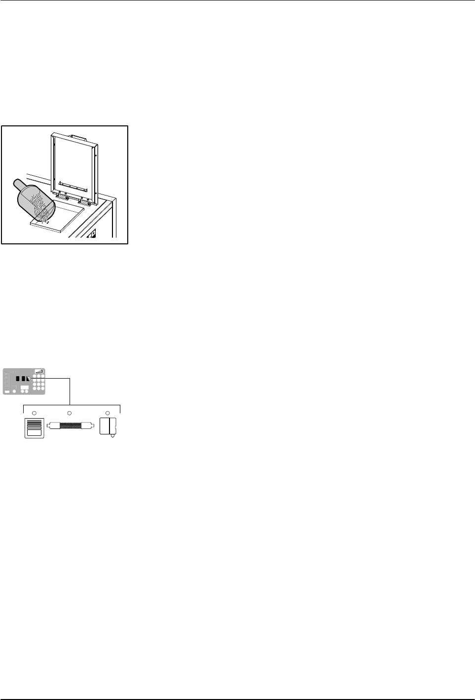
Filling the tank
Component keys
(tank, hose, and applicator)
Operation
4-2
Part 1126931_01
2018 Nordson Corporation
Filling the Tank
CAUTION: Before filling the tank, ensure that tank and material are clean
and free of foreign substances. Foreign substances can hinder functioning or
even cause damage to the melter or accessories.
CAUTION: Cease operation before the tank is completely empty. If there is
too little material in the tank, the material can overheat. Overheated material
can char, collect on surfaces and cause malfunctioning.
1. Use a scoop to pour material into the tank, leaving a minimum of
2.54 cm (1 in.) of space between the top of the material and the top of the
tank.
2. Close the lid after filling the tank.
About Heated Components
The melter contains three groups of heated components. These are the tank
group, which contains tank, the grid, and the reservoir; the hose group; and
the applicator group. Component groups are represented on the control
panel by the component keys shown to the left.
Heated components within each group are identified by their position
number. The position of the tank group is fixed at 1. Hose and applicator
position numbers are automatically assigned based on the hose/applicator
receptacle they are connected to.
NOTE: In some installations, auxiliary devices (such as a heated air
manifold) may be connected to a hose/applicator receptacle. In such cases,
you should label (or otherwise identify) the auxiliary device as to the hose or
applicator position number that represents the device. The control panel will
identify such devices as a hose or applicator, regardless of what the device
actually is.
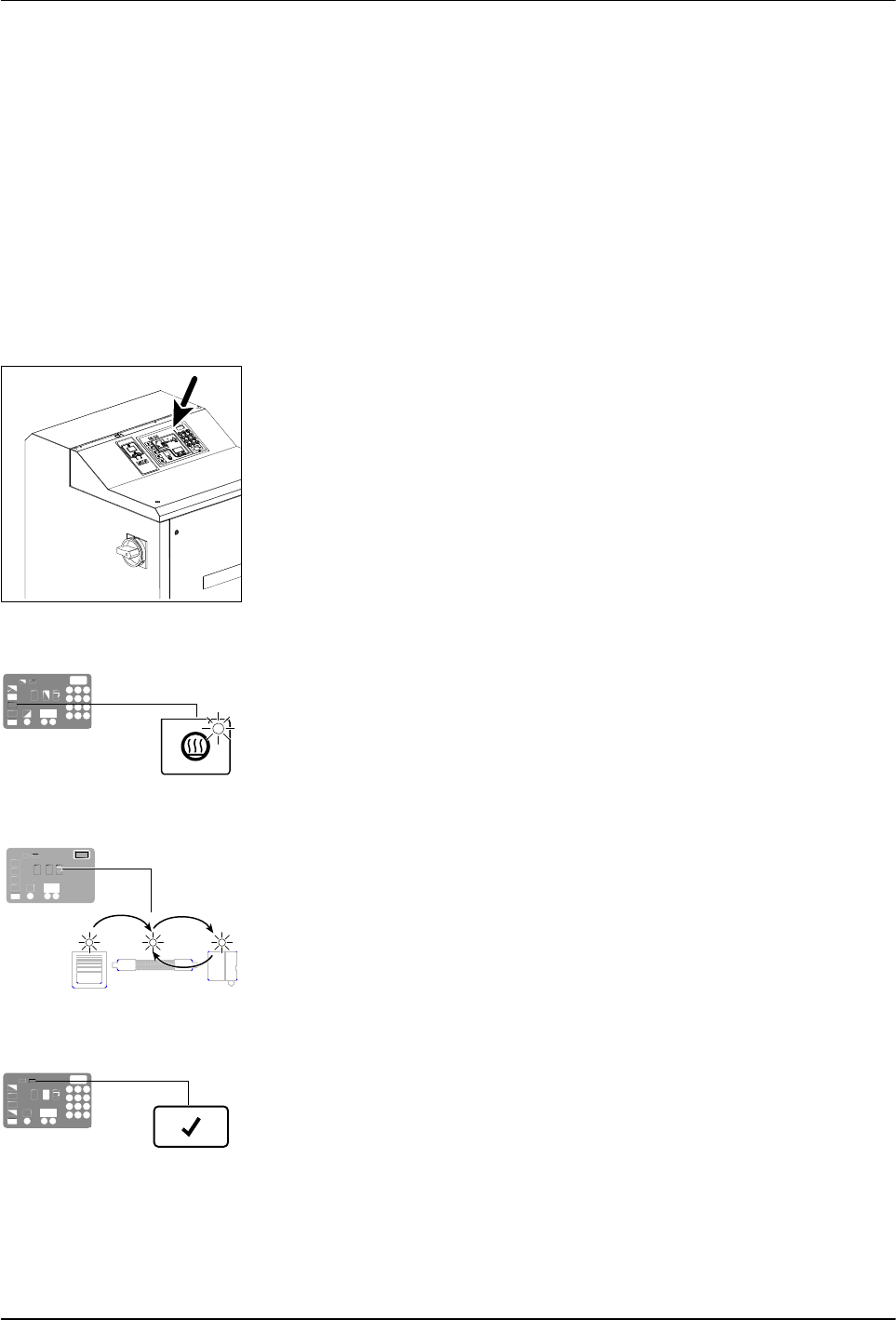
Control switch
Heaters LED
Automatic scan sequence
Ready LED
Operation
4-3
Part 1126931_01
2018 Nordson Corporation
Starting the Melter
Before starting the melter for the first time, confirm that the
melter is fully installed including any required inputs and outputs,
applicator drivers, pattern controllers, or timers.
melter's operating parameters are set up to support the
current manufacturing process.
Refer to Section 3, Installation, if any of the items listed above are
not complete.
To start the melter
1. Place the main power switch in the ON position.
2. Place the control switch in the ON position.
The melter:
Tests the control panel LEDs
Turns on the heaters (the heaters LED turns green)
Begins to automatically scan through and display the
actual temperature of the tank and each hose and applicator that has
a set‐point temperature that is greater than zero degrees. The
sequence of the automatic scan is: tank, each hose and
applicator pair, and then back to the tank.
Turns on the ready LED (green) when the tank and all of the
hoses and applicators are within 3 C (5 F) of their assigned
set‐point temperature.