DuraBlue II Customer Product Manual.pdf - 第67页
Operation 4-5 Part 1126931_01 2018 Nordson Corporation If the melter is switched on when the temperature of the tank is 27 C (50 F) or greater below its assigned set‐point temperature (cold start condition), the re…
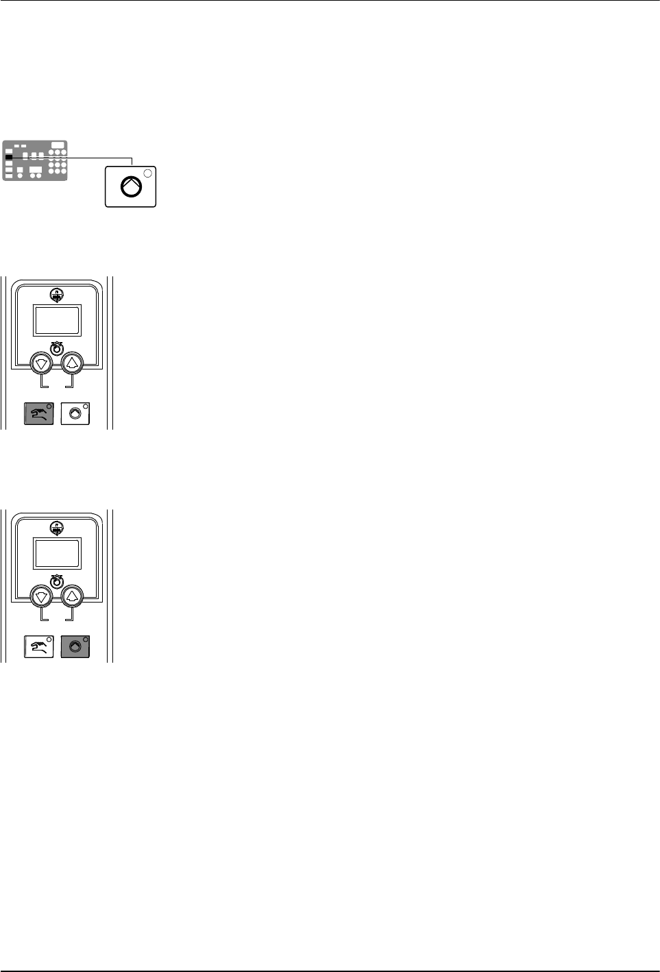
Master pump enable key/LED
Pump mode key and LED
Motor start/stop key and LED
Operation
4-4
Part 1126931_01
2018 Nordson Corporation
Starting the Melter (contd)
CAUTION! Do not operate Nordson pumps without material. Before enabling
the motor(s), ensure that the tank is filled.
3. Press the master pump enable key to enable the pump(s).
The LED on the key turns yellow to indicate that a pump is enabled, but
not running.
4. Melters equipped with the optional motion switch: Place the motion
switch in the ON position.
5. Press the pump mode key(s) to select the manual (LED on) or automatic
(LED off) mode.
6. Press the pump enable key(s) on the motor control panel(s) to enable the
motor(s). The LEDs turn on when a motor is enabled:
Manual Mode—If the system is at ready status (master pump enable key
LED is green) at the time a pump enable key is pressed, then the
motor(s) will start. If the system is not at ready status (master pump
enable key LED is yellow), wait until the LED is green, and then repress
the pump enable key(s).
Automatic Mode—If the system is at ready status (master pump enable
key LED is green) at the time a pump enable key is pressed, then the
motor(s) will start. If the system is not at ready status (master pump
enable key LED is yellow), the motor(s) will start automatically when the
system reaches ready.
NOTE: If any one of standard inputs 1-4 (Parameters 30-33) are being
used and if either control option 3 (Motor 1 Enable/Disable) or control
option 11 (Motor2 Enable/Disable) is selected, the pump enable keys
have no effect. Refer to Setting Up Inputs/Outputs in Section 3,
Installation, for information on connecting and setting up inputs/outputs.

Operation
4-5
Part 1126931_01
2018 Nordson Corporation
If the melter is switched on when the
temperature of the tank is 27 C (50 F) or
greater below its assigned set‐point
temperature (cold start condition), the ready
LED will not turn on until the ready delay
(defined when the melter was set up) has
elapsed.
Appendix B, Parameter 4
The time remaining on the ready delay (in
minutes) appears in the right display at the end
of every scan cycle. When only one minute
remains in the ready delay time, the right
display counts down in seconds.
Appendix B, Parameter 4
You can by‐pass the ready delay time by
pressing the Heaters key twice.
The appearance of F4 in the right display
immediately after the melter is switched on
indicates a problem with the melter's
processor or main board.
Monitor Melter Faults
The appearance of F1 in the right display
immediately after starting the melter indicates
that a hose or applicator cordset may be loose
or disconnected.
Section 6, Troubleshooting
The condition of one or more inputs, may
prevent the heaters from turning on.
Installing Melter Inputs in Section 3,
Installation
If the seven‐day clock feature was set up and
turned on when the melter was last switched
off, the clock will automatically turn on the next
time the melter is switched on.
Function Keys
If a power failure occurs, the melter will restart
in its normal heat‐up cycle, even if the heaters
were off or the melter was in standby prior to
the power failure. If the seven‐day clock was
on prior to the power failure, the melter will
restart in the mode dictated by the clock
schedule at the time the melter restarts.
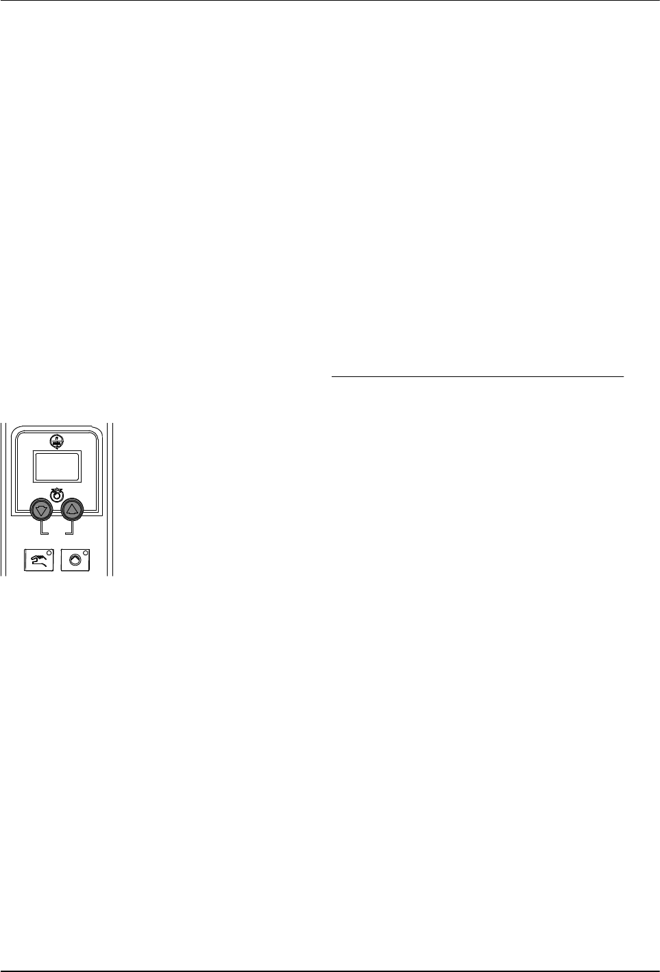
Pump speed arrow keys
Operation
4-6
Part 1126931_01
2018 Nordson Corporation
Manually Adjusting the Pump Speed
When the motor control is set to manual operation, the pump speed can be
adjusted from 0-94 rpm.
NOTE: When the motor control is set to automatic operation, pressing the
motor speed arrow keys will alter the ratio of the line speed reference signal
to allow for fine‐tuning of the adhesive output rate.
Adjust the Motor Speed for Manual Operation
CAUTION! To ensure adequate motor control and cooling, the
recommended minimum pump speed is 18 rpm or greater. To prevent
excessive wear on the pump, avoid prolonged operation of the pump at
speeds greater than 80 rpm.
1. Use the following formula to determine the best pump speed:
pumpspeed[rpm] +
desiredflowrate[gńmin]
adhesivedensity[gńcc] pumpoutputrate[ccńrev]
2. Press the pump speed arrow keys to adjust the motor(s) to the desired
speed (rpm). Each press of an arrow key increases/decreases the motor
speed by 1 rpm.
The current motor speed is indicated on the display.
NOTE: You can change the amount by which the motor speed increases
or decreases (1%, 1 rpm, 0.5 rpm, etc.) upon each press of an arrow key
by changing the value of the motor control SEt parameter. Refer to
Changing a Motor Control Parameter in Section 6, Troubleshooting.