DuraBlue II Customer Product Manual.pdf - 第69页
Pressure control valves Operation 4-7 Part 1126931_01 2018 Nordson Corporation Adjusting Material Pressure The pressure of each material stream can be independently adjusted from 0-103 bar (0-1500 psi). To adjust the p…
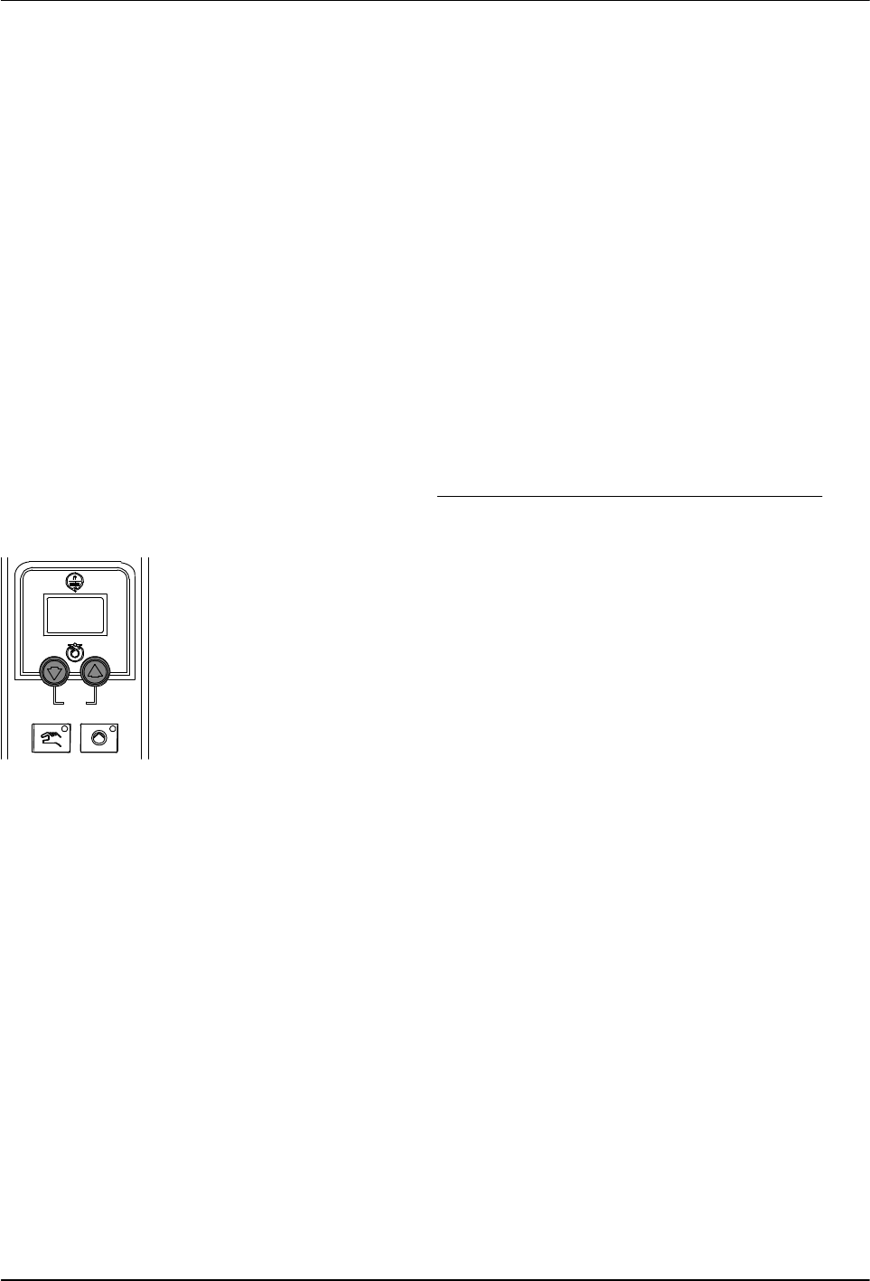
Pump speed arrow keys
Operation
4-6
Part 1126931_01
2018 Nordson Corporation
Manually Adjusting the Pump Speed
When the motor control is set to manual operation, the pump speed can be
adjusted from 0-94 rpm.
NOTE: When the motor control is set to automatic operation, pressing the
motor speed arrow keys will alter the ratio of the line speed reference signal
to allow for fine‐tuning of the adhesive output rate.
Adjust the Motor Speed for Manual Operation
CAUTION! To ensure adequate motor control and cooling, the
recommended minimum pump speed is 18 rpm or greater. To prevent
excessive wear on the pump, avoid prolonged operation of the pump at
speeds greater than 80 rpm.
1. Use the following formula to determine the best pump speed:
pumpspeed[rpm] +
desiredflowrate[gńmin]
adhesivedensity[gńcc] pumpoutputrate[ccńrev]
2. Press the pump speed arrow keys to adjust the motor(s) to the desired
speed (rpm). Each press of an arrow key increases/decreases the motor
speed by 1 rpm.
The current motor speed is indicated on the display.
NOTE: You can change the amount by which the motor speed increases
or decreases (1%, 1 rpm, 0.5 rpm, etc.) upon each press of an arrow key
by changing the value of the motor control SEt parameter. Refer to
Changing a Motor Control Parameter in Section 6, Troubleshooting.

Pressure control valves
Operation
4-7
Part 1126931_01
2018 Nordson Corporation
Adjusting Material Pressure
The pressure of each material stream can be independently adjusted from
0-103 bar (0-1500 psi).
To adjust the pressure, loosen the set screw, and then turn the pressure
adjustment screw clockwise. When the pressure adjustment is set to its full
counterclockwise position, 100% of the material is re‐circulated.

Ready LED
Operation
4-8
Part 1126931_01
2018 Nordson Corporation
Monitoring the Melter
The melter provides indicators that allow you to:
Quickly confirm that the melter is operating correctly
Monitor the actual temperature of the tank group and each hose
and applicator
Monitor the speed of the motor(s)
Identify melter faults
Determine when service is required
The melter automatically determines the number and receptacle of all
hoses and applicators that are connected to it. Refer to Heated Components,
earlier in this section, for information on identification of heated components.
Confirm that the Melter is Operating Correctly
The ready LED turns on (green) when all of the heated components
are within 3 C (5 F) of their set‐point temperature.
The ready LED will not turn on, or will turn off, if any of the following events
occur:
The ready delay is still counting down.
The operator or a remote input places the melter in the standby
mode.
The seven‐day clock places the melter in the standby mode.
There is a fault (the fault LED will turn on).
Refer to Monitor Melter Faults and Using Function Keys in this section for
information about melter faults and using the seven‐day clock and standby
functions. Refer to Parameter 4 in Appendix B, Operating Parameters, for
information about the ready delay.
Heated components with a set‐point
temperature of zero degrees are skipped
during the automatic scan cycle.
The set‐point temperature of the tank and
the pump cannot be set independently.
The time remaining on the ready delay
appears in the right display at the end of each
scan cycle.
Appendix B, Parameter 4
You can override the seven‐day clock at any
time. If the clock has turned the heaters off,
pressing the heaters key will turn the heaters
back on. If the clock has placed the melter into
the standby mode, pressing the standby key
will return the heated components to their
assigned set‐point temperature.
Function Keys