DuraBlue II Customer Product Manual.pdf - 第70页
Ready LED Operation 4-8 Part 1126931_01 2018 Nordson Corporation Monitoring the Melter The melter provides indicators that allow you to: Quickly confirm that the melter is operating correctly Monitor the actual tem…

Pressure control valves
Operation
4-7
Part 1126931_01
2018 Nordson Corporation
Adjusting Material Pressure
The pressure of each material stream can be independently adjusted from
0-103 bar (0-1500 psi).
To adjust the pressure, loosen the set screw, and then turn the pressure
adjustment screw clockwise. When the pressure adjustment is set to its full
counterclockwise position, 100% of the material is re‐circulated.
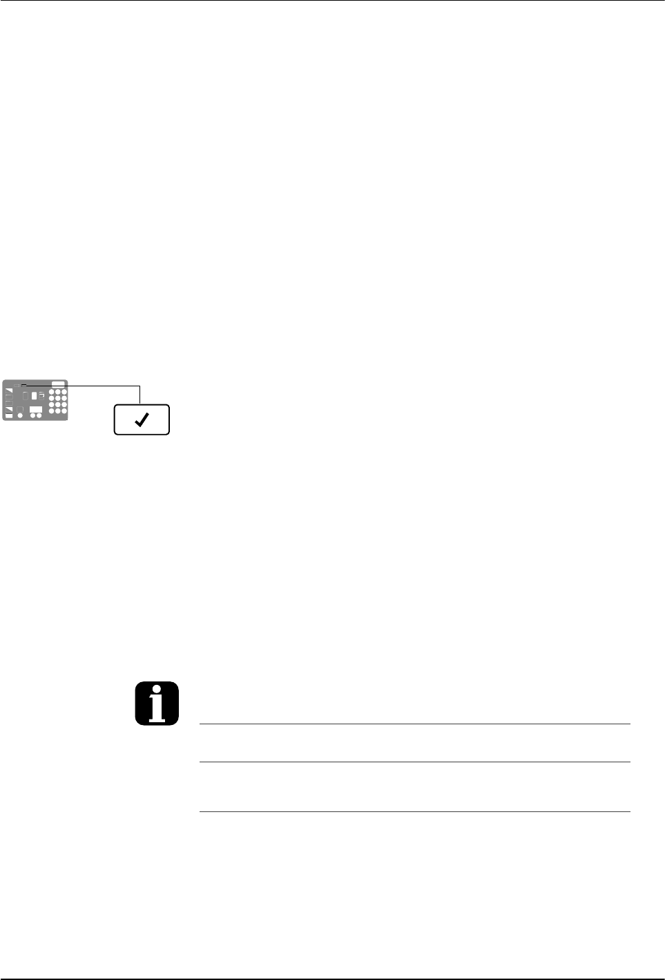
Ready LED
Operation
4-8
Part 1126931_01
2018 Nordson Corporation
Monitoring the Melter
The melter provides indicators that allow you to:
Quickly confirm that the melter is operating correctly
Monitor the actual temperature of the tank group and each hose
and applicator
Monitor the speed of the motor(s)
Identify melter faults
Determine when service is required
The melter automatically determines the number and receptacle of all
hoses and applicators that are connected to it. Refer to Heated Components,
earlier in this section, for information on identification of heated components.
Confirm that the Melter is Operating Correctly
The ready LED turns on (green) when all of the heated components
are within 3 C (5 F) of their set‐point temperature.
The ready LED will not turn on, or will turn off, if any of the following events
occur:
The ready delay is still counting down.
The operator or a remote input places the melter in the standby
mode.
The seven‐day clock places the melter in the standby mode.
There is a fault (the fault LED will turn on).
Refer to Monitor Melter Faults and Using Function Keys in this section for
information about melter faults and using the seven‐day clock and standby
functions. Refer to Parameter 4 in Appendix B, Operating Parameters, for
information about the ready delay.
Heated components with a set‐point
temperature of zero degrees are skipped
during the automatic scan cycle.
The set‐point temperature of the tank and
the pump cannot be set independently.
The time remaining on the ready delay
appears in the right display at the end of each
scan cycle.
Appendix B, Parameter 4
You can override the seven‐day clock at any
time. If the clock has turned the heaters off,
pressing the heaters key will turn the heaters
back on. If the clock has placed the melter into
the standby mode, pressing the standby key
will return the heated components to their
assigned set‐point temperature.
Function Keys

LEDs on component keys
Left display and
scroll key
Component temperature display
Operation
4-9
Part 1126931_01
2018 Nordson Corporation
Monitor Component Temperatures
The actual temperature of each heated component—the tank and each hose
and applicator—can be checked via normal mode or by manually selecting
and checking each component.
By default, the melter remains in the automatic scan mode except when:
The melter is placed into the setup mode
The set‐point temperature of all hoses and applicators is set to zero
degrees
A fault occurs
To check component temperatures using the automatic scan mode
1. When the ready LED is on, observe the LEDs on the component keys.
2. When the LED on the key that represents the desired component
group (tank, hose, or applicator) turns on, observe the left display until it
indicates the position number of the specific component you want to
check.
3. When the position number of the desired component appears in the
left display, observe the right display to determine the component's
actual temperature.
To manually check a component's temperature
1. Press the key (tank, hose, or applicator) that represents the component
group you want to check.
The automatic scan stops and the left display indicates the number of the
first sequential component in the selected component group. The right
display indicates the component's actual temperature.
NOTE: When the tank key is pressed, the left display does not indicate a
component number (blank display).
2. If the first sequential component is not the component you want to check,
use the left‐display scroll key to change to the correct
component number.
The right display indicates the actual temperature of the
selected component.
3. Press the Setup key twice to return to the automatic scan mode.