DuraBlue II Customer Product Manual.pdf - 第75页
Fault LED (red) Operation 4-13 Part 1126931_01 2018 Nordson Corporation 4. The left display indicates, as follows, the component that has, or is, failing. If the LED on the tank key is on, the left display will indic…
Operation
4-12
Part 1126931_01
2018 Nordson Corporation
Table 4‐1 Melter Faults (contd)
Display
Code/Sub‐code
Name Affect on Melter Cause Corrective Action
F4/7
Analog‐to‐digital
calibration
Melter stops
functioning
Failed hose or
applicator
RTD analog‐to‐digital
converter could not be
calibrated (grounded
RTD in system)
Replace hose or
applicator. Note: Set
setpoint to zero to avoid
F1 fault.
Replace main board or
ribbon cable, or CPU
F4/8
Main board
feedback
Melter stops
functioning
Communication failure
between main board
and CPU
Replace main board,
ribbon cable, or CPU
F4/9
Expansion board
feedback
Melter stops
functioning
Communication failure
between expansion
board and main board
Check the ribbon cable
connections between
the expansion board
and the main board.
F4/A Thermostat
Melter stops
functioning
Tank or manifold
thermostat is open
Replace thermostat, J7
harness, or main board
F4/d
Communications
with optional I/O
card
Heaters remain on,
but fault condition
persists
Communication failure
between CPU and the
optional I/O card
Replace the I/O card or
CPU
F4/E
Fieldbus
communications
failure
Alert output (if output
option 6 is selected)
Melter continues to
operate normally.
Fieldbus card failure.
Replace the Fieldbus
card
F1, F2 and F3 Faults
When the melter detects an F1, F2, or an F3 fault:
1. The automatic scan stops and the melter begins to monitor the potential
fault for up to two minutes. The ready and heater LEDs remain on during
the two‐minute time period. If, at any time during the two‐minute period,
the melter detects that the fault condition no longer exists, the melter will
return to the automatic scan mode.
2. The LED on the affected component key (tank, hose, or applicator) turns
on to indicate the type of component that has, or is, failing.
3. The right display indicates the type of fault (F1, F2, or F3).
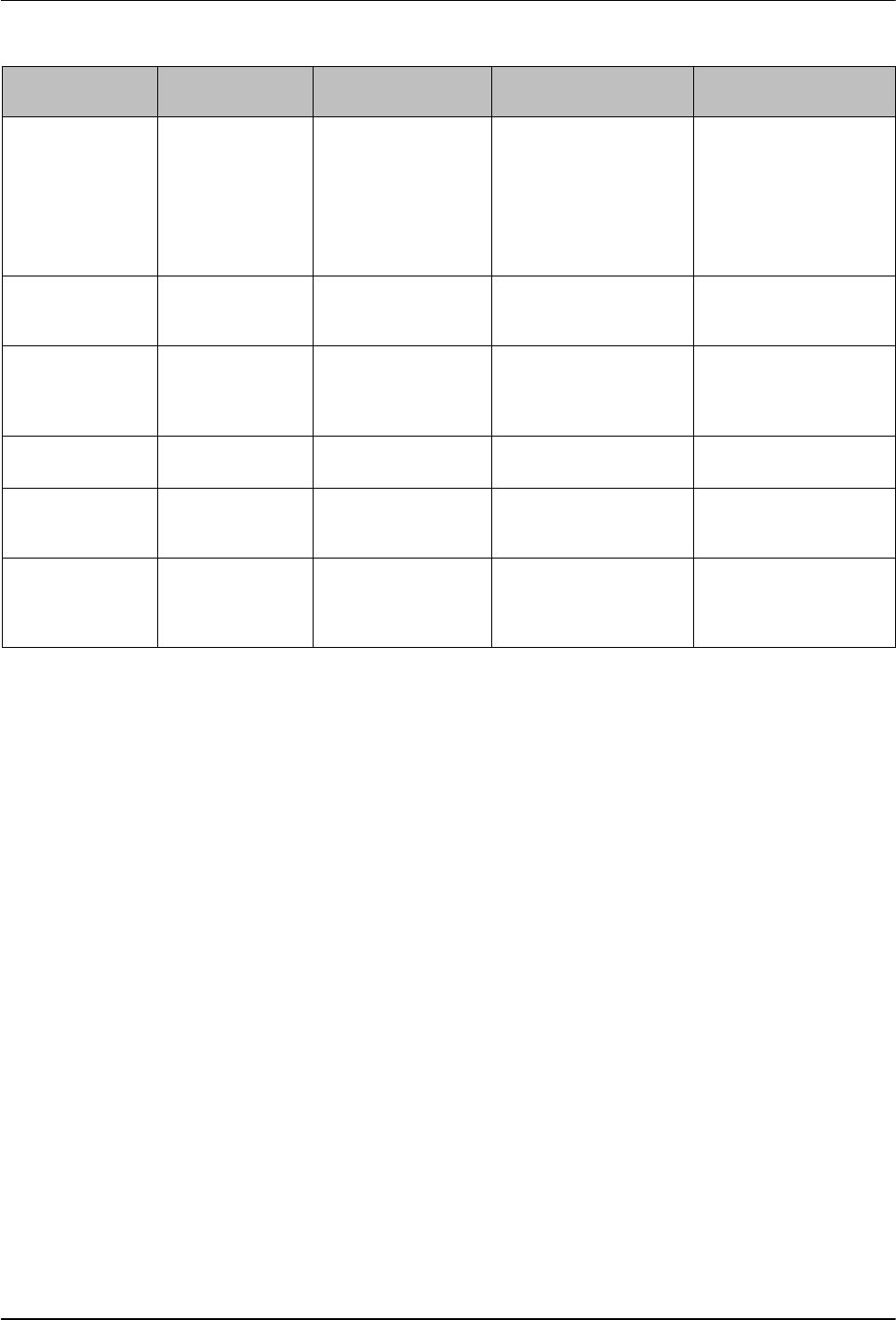
Fault LED (red)
Operation
4-13
Part 1126931_01
2018 Nordson Corporation
4. The left display indicates, as follows, the component that has, or is,
failing.
If the LED on the tank key is on, the left display will indicate either 1
for the tank or 2 for the pump.
If the LED on the hose or applicator key is on, the left display will
indicate the number of the affected hose or applicator.
5. If the fault condition still exists at the end of the two‐minute monitoring
period, the ready LED will turn off, the red fault LED will turn on, the
heaters turn off, and the melter records the fault in the fault log. Refer to
Monitor Melter Faults in this section.
To be able to put the melter back into operation, the fault must be remedied
and the melter reset (reset key). Refer to Section 6, Troubleshooting, for
information about diagnosing and correcting fault conditions. Also refer to
Returning the Melter to Factory Settings.
To view the temperature of a heated component
when an F2 or F3 fault exists, simultaneously
press and hold both of the right‐display scroll
keys.
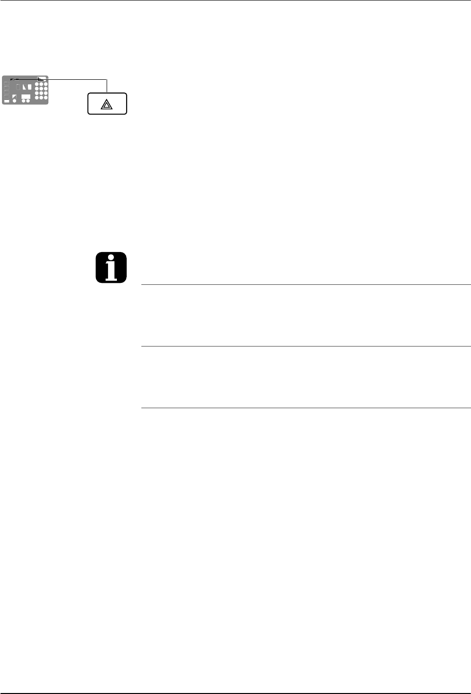
You can temporarily dismiss an F1fault (RTD)
and return to the automatic scan mode by
pressing the Clear/Reset key. The heaters will,
however, remain off. If the fault condition still
exists two minutes after pressing the clear/reset
key, the fault LED will turn back on.
When an F1 fault code appears, you can
determine whether the fault was caused by an
open or a shorted RTD by simultaneously
pressing both of the right‐display scroll keys. If
the right display indicates OP, the RTD is open, if
it indicates SH, the RTD has shorted.
If, for any reason, a component reaches 235 C
(458 F), an immediate F3 fault will occur (no
two‐minute monitoring period).
Clear/Reset key
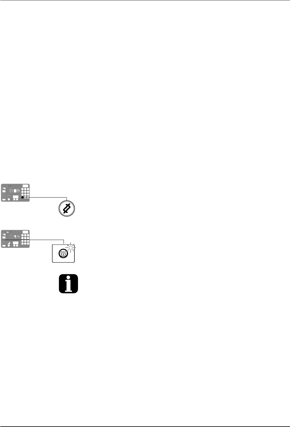
Heater key
Operation
4-14
Part 1126931_01
2018 Nordson Corporation
F4 Fault
When the melter detects an F4 fault:
1. The ready LED turns off and the red fault LED turns on.
2. All of the component key LEDs (tank, hose, and applicator) turn off.
3. The right display indicates F4.
4. The left display indicates a sub‐code. Sub‐codes classify the fault as
being fatal or nonfatal. The affect on the melter of each of these two
classes of F4 faults is:
Fatal—The fault LED turns on and stays on and the melter stops
functioning completely.
Nonfatal—The fault LED turns on for five seconds, but the heaters and
pump continue to operate normally. Nonfatal faults affect the internal
clock.
5. The melter records the fault in the fault log. Refer to Monitor Melter Faults
in this section.
Resetting the melter
1. Diagnose and correct the fault condition. Refer to Section 6,
Troubleshooting, for information about diagnosing and correcting fault
conditions.
2. Return the melter to the automatic scan mode by pressing the Setup key
twice.
3. Press the Clear/Reset key.
4. Press the Heater key to turn on the heaters.
If F4 appears in the right display when you press the clock key, the internal clock function
has failed.