DuraBlue II Customer Product Manual.pdf - 第78页
Operation 4-16 Part 1126931_01 2018 Nordson Corporation Fault Log examples Example 1: An unused log entry. Example 2: If the LED on the tank key were on, this log entry would indicate that the tank is under temperature…
Setup Key
Left display and scroll key
Scrolling through the fault log
Operation
4-15
Part 1126931_01
2018 Nordson Corporation
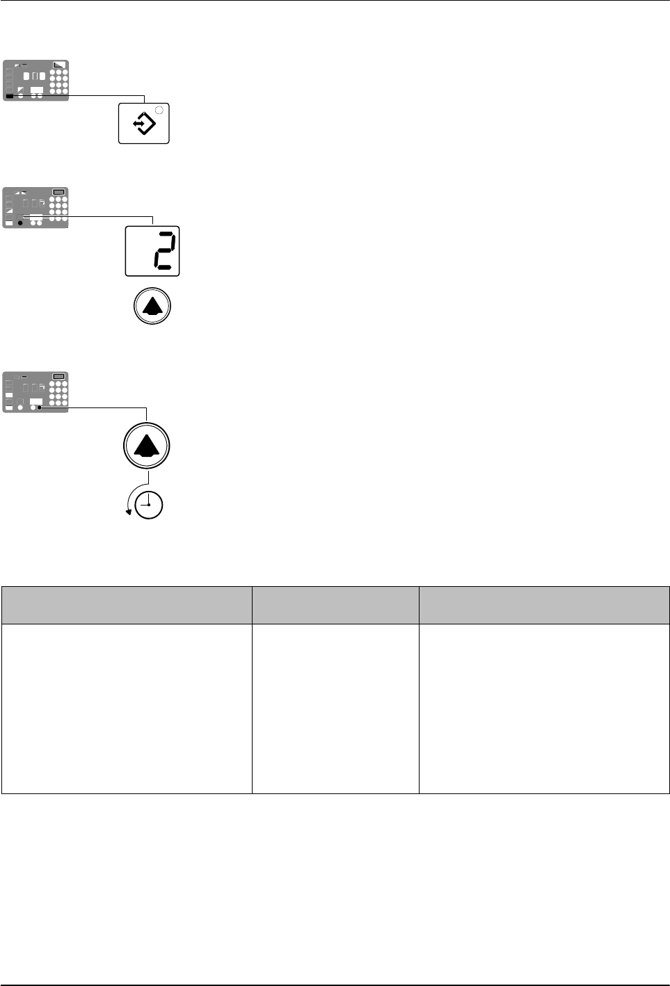
Reviewing the Fault Log
1. Press and hold the Setup key.
The automatic scan stops and operating Parameter 1 appears in the
left display.
2. Scroll the left display to Parameter 2 (the fault log).
The right display indicates the last fault that occurred as follows:
If the last fault was an F1, F2, or F3 fault, then the LED on the affected
component key turns yellow.
If the last fault to occur was an F4 fault, then the LEDs on all of
the component keys turn off.
The right display indicates the log entry for the last fault to
occur. Table 4‐2 provides the meaning of each digit in the log
entry. Following the table are two example fault log entries.
3. Press the right‐display scroll key to review each of the remaining nine log
entries. Each press of the scroll key displays a progressively older log
entry.
NOTE: The fault log only stores the last ten faults. After ten faults
occur, the existing log entries are overwritten, beginning with the oldest
entry, by the eleventh and following log entries.
4. Press the Setup key to return to the automatic scan mode.
Table 4‐2 Fault Log
First Digit Second and Third
Digits
Fourth Digit
Component:
‐ F
Type of fault:
1 = Tank or hose/applicator 1 0 = Unused log entry
2 = Pump or hose/applicator 2 1 = RTD (open or short)
3 = Hose 3 or applicator 3 2 = Component under temperature
4 = Hose 4 or applicator 4 3 = Component over temperature
5 = Hose 5 or applicator 5
4 = Processor or electrical failure
6 = Hose 6 or applicator 6
Operation
4-16
Part 1126931_01
2018 Nordson Corporation
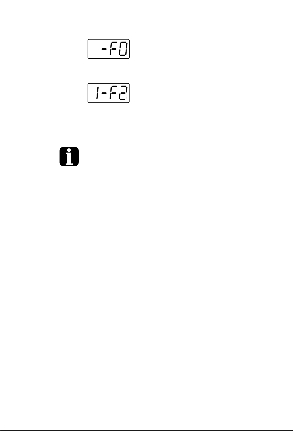
Fault Log examples
Example 1:
An unused log entry.
Example 2:
If the LED on the tank key were on, this log entry
would indicate that the tank is under temperature. If the LED on the hose key
were on, this log entry would indicate that hose 1 is under temperature.
To view the number of heater hours that have
elapsed since a log entry was created,
simultaneously press both of the right‐display
scroll keys. The hours are indicated in the right
display.
The melter will return to the automatic scan mode
if the fault log is left open for a period of two
minutes without any key being pressed.
When an F1 fault is the result of a
hose/applicator pair being disconnected from the
melter, two fault log entries are created. The first
entry is for the applicator and the second entry is
for the hose.
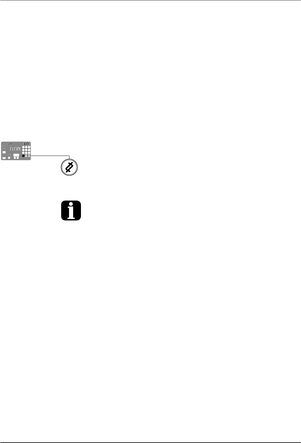
Clear/Reset key
Operation
4-17
Part 1126931_01
2018 Nordson Corporation
Monitor the Service Interval
The melter can be set up so that the service LED located on the left side
of the control panel turns on after a customer‐defined time period has
elapsed. The service LED may be used to signal the need to change the
hot melt filter or to complete any other customer‐specified maintenance
activity. Once the specified maintenance is performed, the service LED must
be reset.
To reset the service LED
With the melter in the scan mode, press the Clear/Reset key to turn off the
service LED and reset the service interval time.
The default setting for the service interval time is 500 hours, refer to Parameter 5 in
Appendix B.