DuraBlue II Customer Product Manual.pdf - 第97页
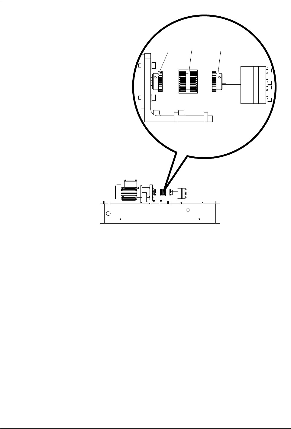
Service 5-7 Part 1126931_01 2018 Nordson Corporation 1 3 2 Figure 5‐2 Coupling assembly components 1 Motor coupling hub 2 Coupling sleeve 3 Pump coupling hub 6. Remove the protective coating from the new motor shaft, s…

Service
5-6
Part 1126931_01
2018 Nordson Corporation
Replacing a Motor or Coupling
Follow this procedure to replace a motor or coupling. You will need the
following items:
appropriate tools
replacement motor or coupling
anti‐seize lubricant (if needed)
1. Disconnect and lock out electrical power to the melter.
2. Remove the hydraulic side covers and the left and right control cabinet
side covers. Refer to Detaching the Exterior Panels earlier in this section
as needed.
3. Disconnect the motor cable wires, noting their terminal positions.
4. See Figure 5‐2. Loosen the screws that secure the motor to the base of
the melter and then slide the motor back.
5. Slide the coupling sleeve (2) off of the coupling hubs (1 and 3), loosen
the hub set screws, and remove the hubs.
Service
5-7
Part 1126931_01
2018 Nordson Corporation
1
3
2
Figure 5‐2 Coupling assembly components
1 Motor coupling hub
2 Coupling sleeve
3 Pump coupling hub
6. Remove the protective coating from the new motor shaft, slide the
replacement (if applicable) motor coupling hub onto the motor shaft, and
tighten the hub set screws.
7. Install the replacement (if applicable) pump coupling hub on the pump
shaft, ensure that it is flush with the pump shaft, and tighten the hub set
screws.
8. Loosely install the replacement motor assembly and slide the assembly,
including the motor coupling hub and sleeve, toward the pump until the
coupling sleeve engages with pump coupling hub.
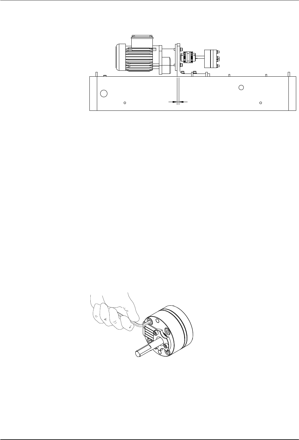
9. Ensure that the coupling sleeve cannot move, then slide the motor
assembly back 4 mm (0.16 in.), as indicated in Figure 5‐3.
Service
5-8
Part 1126931_01
2018 Nordson Corporation
Replacing a Motor or Coupling (contd)
4 mm (0.16 in.)
Figure 5‐3 Moving the motor assembly back 4 mm (0.16 in.)
10. Tighten the screws that secure the motor to the base of the melter
11. To ensure proper motor and pump shaft alignment, ensure that you can
freely slide the coupling sleeve back and forth by about 4 mm (0.16 in.)
each way.
12. Reconnect the motor cable wires to the same terminals from which they
were disconnected.
13. Reinstall the melter covers and restore the system to normal operation.
Pump
Tightening the Pump Screws
1. Ensure that the melter is turned off and that power has been
disconnected and locked out.
2. Ensure that the melter, tank, manifold, and pump are cold.
3. See Figure 5‐4. Tighten the screws to 25 Nm (222 in.‐lb).
Figure 5‐4 Tightening the pump screws
4. Restore the system to normal operation.