OM-1833-001w_SL.pdf - 第101页
6.3.2 Referential Dimension for T aping (8 mm Embossed) Embossed Carrier T ype T aping Cover T ape T aped Component (Sprocket Hole) Direction of Unreeling Cover T ape Sprocket Hole Reel Embossed Carrier T ape Embossed Ho…
(b) The above specications do not imply any guarantee of pick-up rate, etc.
The pick-up rate varies depending on how the main machine is adjusted
and the combination of the main machine and the tape feeders.
(c) The clearance between the centerlines of the cavity and the sprocket hole
should be 0.05 mm or less.
(d) 10 pitches cumulative tolerance P
0
should be ± 0.2 mm.
(e) The cover tape should run smoothly along the sprocket holes.
The edges of the cover tape should be aligned with the carrier tape (taping).
The thickness of the cover tape should be 0.07 mm or less (including waste
paper).
(f) Use a taping on condition that the component itself or its electrical contact
is not protruded from the upper surface of tape.
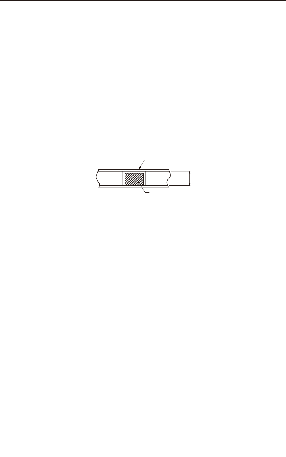
Paper Taping
"Tape thickness (T) > Component thickness"
Cover Tape
Component
T
Fig. F4
(g) The shape of component pick-up surface should be wide and smooth
enough to be picked up by vacuum nozzles.
(h) Cover tapes sometimes become thicker than expected due to leafy and
uffy leftovers produced through the production process.
However, the overall thickness should not exceed the value described as
"T
2
" in the table.
1504-001
6.3 Referential Dimension for Taping
OM-1833
6-4
6.3.2 Referential Dimension for Taping (8 mm Embossed)
Embossed Carrier Type Taping
Cover Tape
Taped Component
(Sprocket Hole)
Direction of Unreeling
Cover Tape
Sprocket Hole
Reel
Embossed Carrier Tape
Embossed Hole
Component
Compartment
Fig. F5 Fig. F6
Table F4
Cover Tape
Processing
Section
Type
Tape Width
×
Feed Pitch
(mm)
Dimensions for Taping (mm)
A
0
B
0
W F E P
1
P
2
P
0
D
0
T T
2
K D
1
C t
S 8×2
More
than
0.2 to
0.6 or
less
More
than
0.4 to
1.2 or
less
8.0
±
0.1
3.5
±
0.05
1.75
±
0.1
2.0
±
0.05
2.0
±
0.05
4.0
±
0.05
φ
1.5
+
0.1
0
0.16
or more
0.3
or less
2.5
or less
2.4
or less
0.5
or more
3.0
or less
+
0.2
to
- T
(g)
M 8×2
More
than
0.4 to
1.6 or
less
More
than
0.7 to
1.7 or
less
8.0
±
0.1
3.5
±
0.05
1.75
±
0.1
2.0
±
0.05
2.0
±
0.05
4.0
±
0.05
φ
1.5
+
0.1
0
0.16
or more
0.3
or less
2.5
or less
2.4
or less
0.5
or more
3.0
or less
+
0.2
to
- T
(g)
M 8×4
More
than
1.6 to
3.4 or
less
More
than
0.7 to
1.7 or
less
8.0
±
0.1
3.5
±
0.05
1.75
±
0.1
4.0
±
0.05
2.0
±
0.05
4.0
±
0.05
φ
1.5
+
0.1
0
0.16
or more
0.3
or less
2.5
or less
2.4
or less
0.5
or more
3.0
or less
+
0.2
to
- T
(g)
L 8×2
More
than
0.6 to
1.6 or
less
More
than
1.7 to
2.5 or
less
8.0
±
0.1
3.5
±
0.05
1.75
±
0.1
2.0
±
0.05
2.0
±
0.05
4.0
±
0.05
φ
1.5
+
0.1
0
0.16
or more
0.3
or less
2.5
or less
2.4
or less
0.5
or more
3.0
or less
+
0.2
to
- T
(g)
L 8×4
More
than
1.6 to
3.4 or
less
More
than
1.7 to
2.5 or
less
8.0
±
0.1
3.5
±
0.05
1.75
±
0.1
4.0
±
0.05
2.0
±
0.05
4.0
±
0.05
φ
1.5
+
0.1
0
0.16
or more
0.3
or less
2.5
or less
2.4
or less
0.5
or more
3.0
or less
+
0.2
to
- T
(g)
LL 8×4
More
than
1.6 to
3.4 or
less
More
than
2.5 to
3.7 or
less
8.0
±
0.1
3.5
±
0.05
1.75
±
0.1
4.0
±
0.05
2.0
±
0.05
4.0
±
0.05
φ
1.5
+
0.1
0
0.16
or more
0.3
or less
2.5
or less
2.4
or less
0.5
or more
3.0
or less
+
0.2
to
- T
(g)
Note
(a) A
0
×
B
0
stands for the rectangle hole size on the tape.
The clearance between a rectangle hole and a component affects the pick-
up rate.
Use the taping component with appropriate clearance specications.
(b) The above specications do not imply any guarantee of pick-up rate, etc.
The pick-up rate varies depending on how the main machine is adjusted
and the combination of the main machine and the tape feeders.
(c) Make a hole (D
1
) in the cavity if necessary.
(d) 10 pitches cumulative tolerance P
0
should be ± 0.2 mm.
1504-001
6.3 Referential Dimension for Taping
OM-1833
6-5
(e) The cover tape should run smoothly along the sprocket holes.
The edges of the cover tape should be aligned with the carrier tape (taping).
The thickness of the cover tape should be 0.07 mm or less (including waste
paper).
(f) Use a taping on condition that the component itself or its electrical contact
is not protruded from the upper surface of tape.
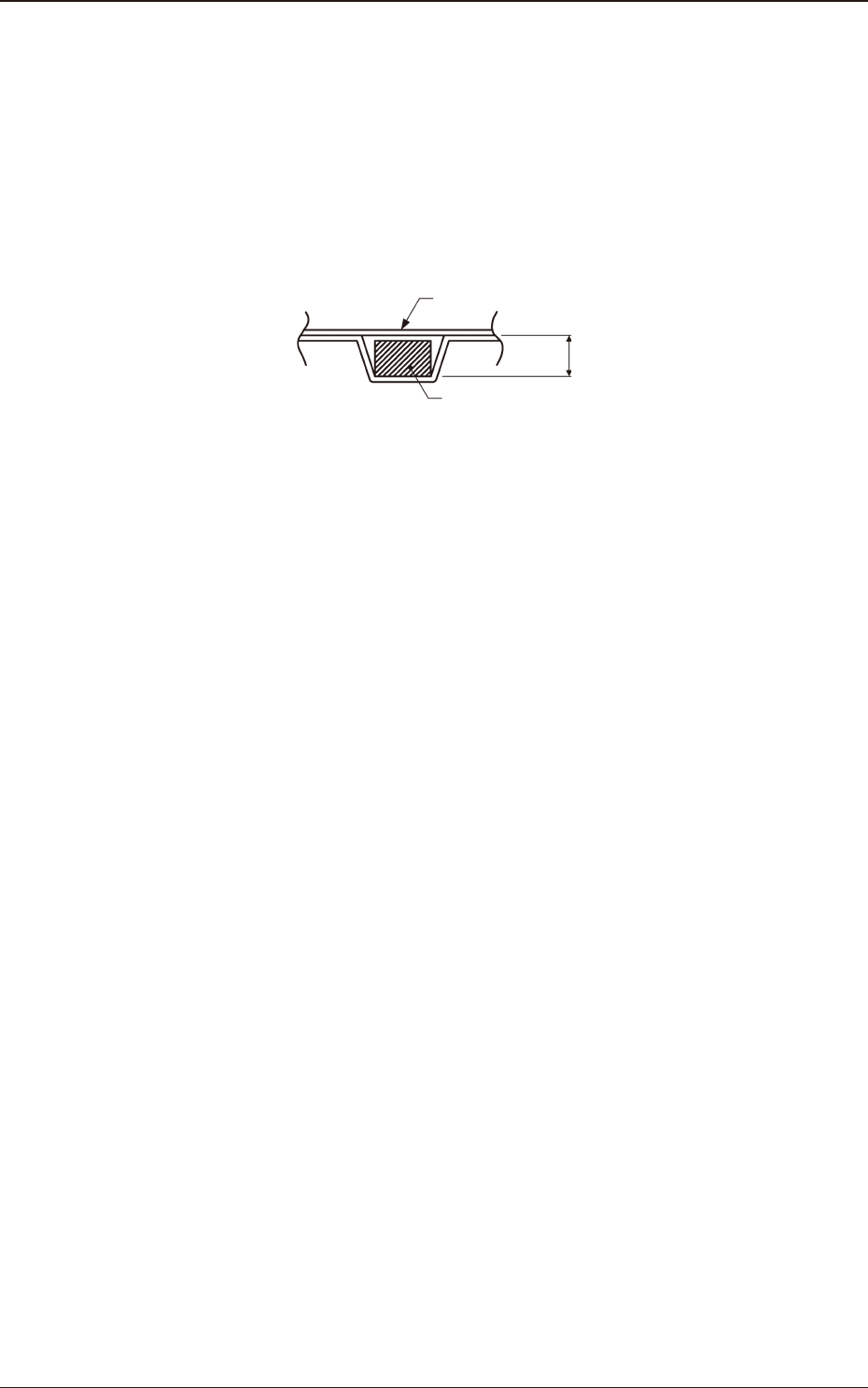
Embossed Taping
"Embossed depth (T
3
) > Component thickness"
Cover Tape
Component
T3
Fig. F7
(g) Shown in column "t" is the gap between the component pick-up and chute
surfaces.
As the gap can be adjusted by the stroke control, set the pick-up level data
in the component library data.
If dimension "t" is big, components may not stay still or may be tilted.
Be sure to adjust the dimension for the appropriate one in the range of
values specied in the table.
(h) The shape of component pick-up surface should be wide and smooth
enough to be picked up by vacuum nozzles.
(i) Cover tapes sometimes become thicker than expected due to leafy and
uffy leftovers produced through the production process.
However, the overall thickness should not exceed the value described as
"T
2
" in the table.
1504-001
6.3 Referential Dimension for Taping
OM-1833
6-6