OM-1833-001w_SL.pdf - 第104页
7.3 Leader Section (T ape End Section) The tape length in the leader section should be 400 mm or more including the empty component compartment. Such empty component compartment should be sealed with a cover tape for 100…
7. Reference Taping Specications
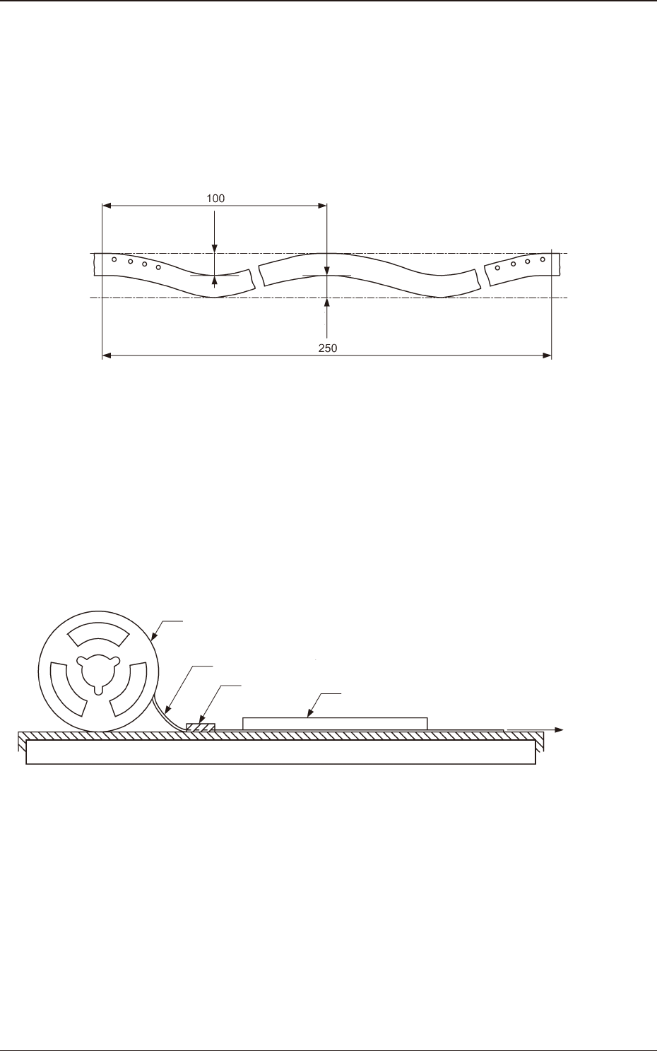
7.1 Allowable Limit of Edge Waving of Tape
Allowable limit of edge waving of tape should be or less than 1 mm per 100 mm
through a length of 250 mm as illustrated.
1 or less
1 or less
Unit : mm
Fig. G1 Allowable Limit of Edge Waving of Tape
7.2 Test Method for Edge Waving of Tape
The edge waving of tape shall be tested in such a manner that one end of tape
is xed, the tape is pulled by a force of 1N (102 gf) applied to the other end, a
graduated transparent plastic plate which also serves as a weight is placed on the
tape, and then the waving is measured.
Tape
Reel
Fixed Point
Graduated transparent plastic plate
which also serves as weight
Force of 1N
(102 gf)
Fig. G2 Test Method for Edge Waving of Tape
1504-001
7. Reference Taping Specications
OM-1833
7-1
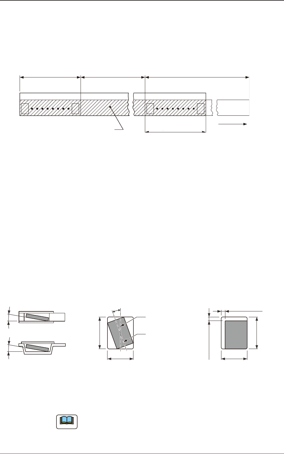
7.3 Leader Section (Tape End Section)
The tape length in the leader section should be 400 mm or more including the
empty component compartment. Such empty component compartment should be
sealed with a cover tape for 100 mm or more.
Trailer (160 mm min.)
(400mm or less)
Portion Equipped with Surface
Mounting Component
Leader (400 mm min.)
Cover Tape
Empty Component
Compartment
Empty Component
Compartment
(100 mm min. Seal)
Direction of Unreeling
Fig. G3
7.4 Trailer Section (Tape Trailer Section)
The tape length of the trailer section, including the embossed or square punched
hole carrier tape that does not contain components, should be greater than 160 mm
and less than 400 mm.
The empty component compartment should be sealed with a cover tape.
The last portion of carrier tape shall release from the reel hub.
7.5 Position of Taped Component
B
0
Center Line of
Component Compartment
Center Line of
Component
(Note)
20° or less (tape width 8 mm)
Top ViewSide Sectional View or
Front Sectional View
Component Revolution in
Horizontal Direction
Component Inclination
10° or less10° or less
B0
A0
(Note)
0.5 mm or less
(Note)
0.5 mm or less
Top View
Component Bias in
Horizontal Direction
A0
Fig. G4
Note
When the direction of a component is changed in the square punched hole or
embossed tape hole, the component can not be picked up easily. In such case,
keep an appropriate clearance around the component in the hole.
1504-001
7.3 Leader Section (Tape End Section)
OM-1833
7-2
7.6 Strength of Carrier and Cover Tapes
Carrier Tape
When a tensile force of 10 N (1.02 kgf) is applied in the direction of unreeling
the tape, the tape shall withstand this force.
Cover Tape
When a tensile force of 10 N (1.02 kgf) is applied to the tape, the tape shall
withstand this force.
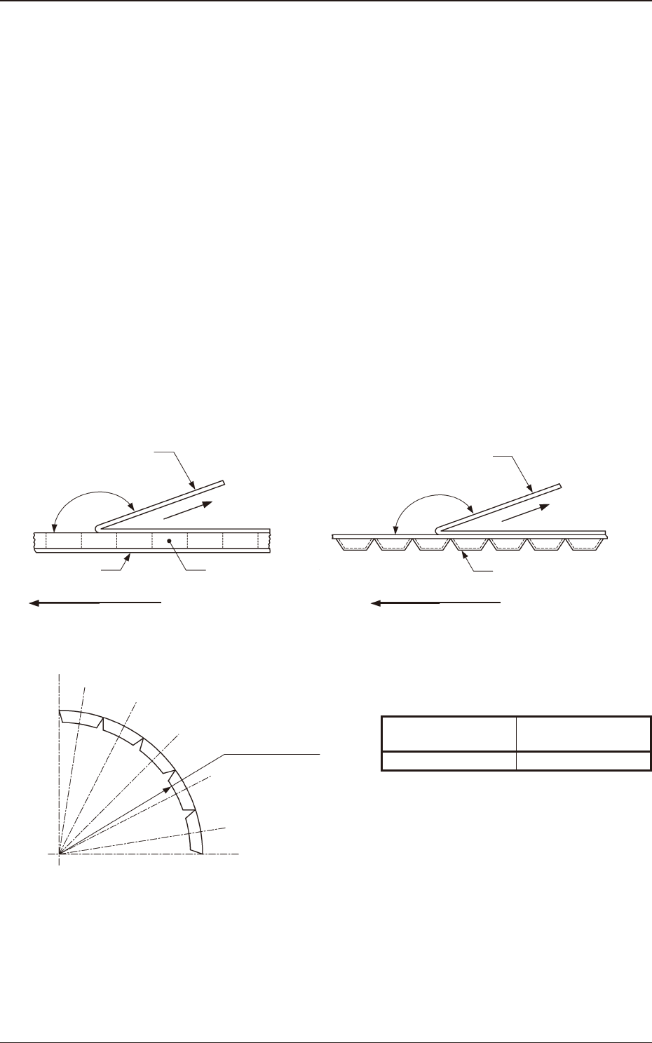
7.7 Peel Strength of Cover Tape
The direction of the cover tape peeling force should be maintained at an angle of
165 to 180 degrees.
When the cover tape is peeled off at the speed of 300 mm/min ± 10 mm/min, the
cover tape peeling force should be 0.1 to 0.7 N (10.2 to 71.4 gf).
Rectangle Hole Punched Carrier Type Taping Embossed Carrier Type Taping
Cover Tape
Direction of Peel off
Rectangle Hole
Punched Carrier Tape
Bottom Cover Tape
Direction of Unreeling
165° to 180°
Cover Tape
Direction of Peel off
Direction of Unreeling
Embossed Carrier Tape
165° to 180°
Fig. G5 Angle in Peel Test Fig. G6 Angle in Peel Test
7.8 Minimum Bending Radius
1504-001
Fig. G7 Minimum Bending Radius
Width of Tape and Minimum Bending Radius
Table G1
Width of Tape
(mm)
Minimum Bending
Radius (mm)
8 30
When the tape is bent with the minimum bending radius, the tape shall not be
damaged, the components shall maintain their position and direction in the tape
and shall be free from abnormalities such as damage.
Minimum Bending
Radius (R)
7.6 Strength of Carrier and Cover Tapes
OM-1833
7-3