OM-1833-001w_SL.pdf - 第22页
1.2 Constraints • For components in the emboss tape where the component posture becomes unstable in the carrier tape pocket during the tape feeding operation, automatic deceleration of the tape feeding speed is performed…

1504-001
1. Scope
This SL tape feeder (Super Loading Tape Feeder) has been designed for supplying
the taped chip components to the chip mounter.
1.1 Main Features
•
Tape Automatic Loading Function
Setting the tape to be attached, onto the specied position in the feeder and
pressing the Loading button, takes the tape into the feeder automatically to
complete the tape setup.
The time for the complicated tape setting work can be saved with this
automatization. The removal and collection of the tape is quite easy with the
tape unload-ing function that draws the tape to this side.
•
New type cover tape processing mechanism has been employed.
When the new processing system where the cover tape is fed and disposed of
together with carrier tape, is employed, cover tape collection work becomes
unnecessary. Reducing paper ber generation and stabilized component feeding
accuracy improves the operator’s ability to control the process, and enhances
stable component pick-up and placement quality.
•
Component Reload (No need of splicing)
Physically connecting the succeeding component supply tape with the splicing
tape is not required. Under the condition that the proceeding tape has been
setup, the succeeding component supply tape can be setup anytime.
Also, the component reload on the lane where the component shortage has
occurred, can be performed without pulling out the feeder from the main
machine.
•
Trial Tape Usable
A short trial tape can be setup.
•
Usable of Paper and Emboss Tape together
Paper tape can be used together with Emboss tape.
•
Applicable Machines
This tape feeder can be mounted on the SIGMA-F8, SIGMA-G5/G5S series,
and GXH series machines.
1. Scope
OM-1833
1-1
1.2 Constraints
•
For components in the emboss tape where the component posture becomes
unstable in the carrier tape pocket during the tape feeding operation, automatic
deceleration of the tape feeding speed is performed. Also, for the component
(thickness: 0.7 mm or more) in thick paper tape, the tape feeding speed is
automatically reduced.
The following new control data is included in the component library data.
Table A1
Control Data (New) Default
SL Feeder Automatic
Speed Reduction
Disable ●
Enable
* Embossed tape components: 95% speed reduction
Thick paper tape components
(component dimension thickness 0.7 mm or more): 30% speed reduction
You may operate with the speed reduction value decreased or disabled only in
the case of components for which you have veried that disabling tape feed
speed (automatic speed reduction) will not cause a problem. In this case, if you
change the SL feeder automatic speed reduction to “disabled,” the original tape
feed speed will be applied.
Table A2
Control Data Default
Tape Feeding Speed
Reduction
0 to 99 % 0
•
There should not be any vacant slot on either side of the SL feeder installation lane.
Since it is possible for the inside of the machine cutter guide to be jammed with
discarded tape, it must be cleaned periodically (about once a week).
•
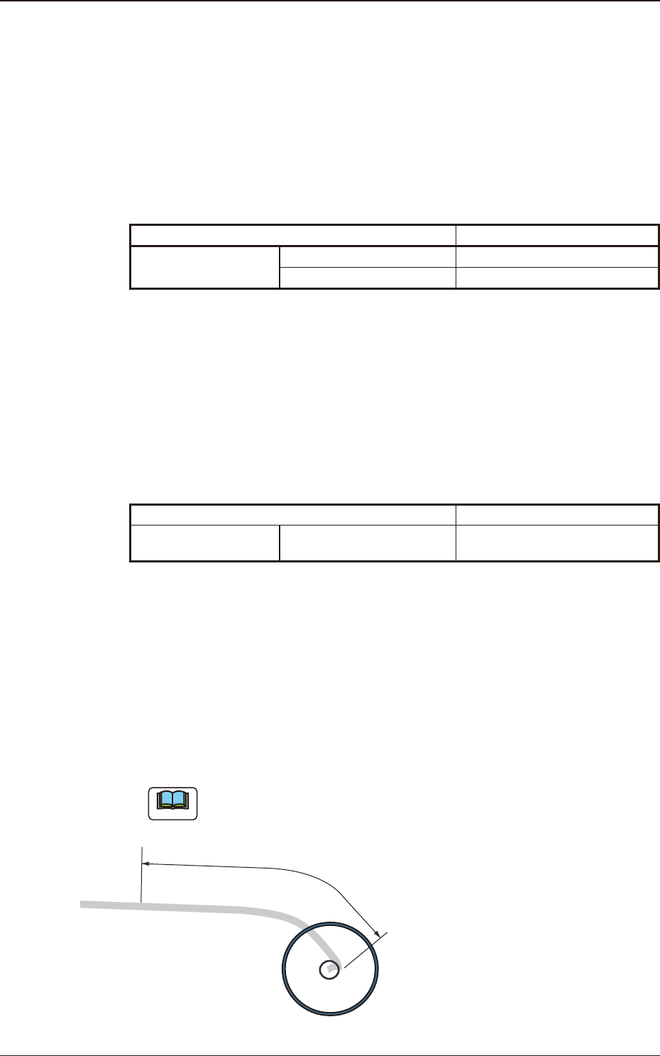
The length of the tape end section without any component (tape section sealed
with cover tape), should be 400 mm or less.
(For a component size of more than 400 mm, tape end detection is not available.
Therefore, the tape cannot be replaced automatically with the following tape to
supply components. Take out the tape with the unloading operation after the machine
is stopped because of continuous pick-up errors due to there being no component.
Note
For taping standards, the component size should be 160 mm or more and
there is no upper limit.
The length of the tape end section without
any component should be 400 mm or less.
Fig. A1
1504-001
1.2 Constraints
OM-1833
1-2
1504-001
1.2 Constraints
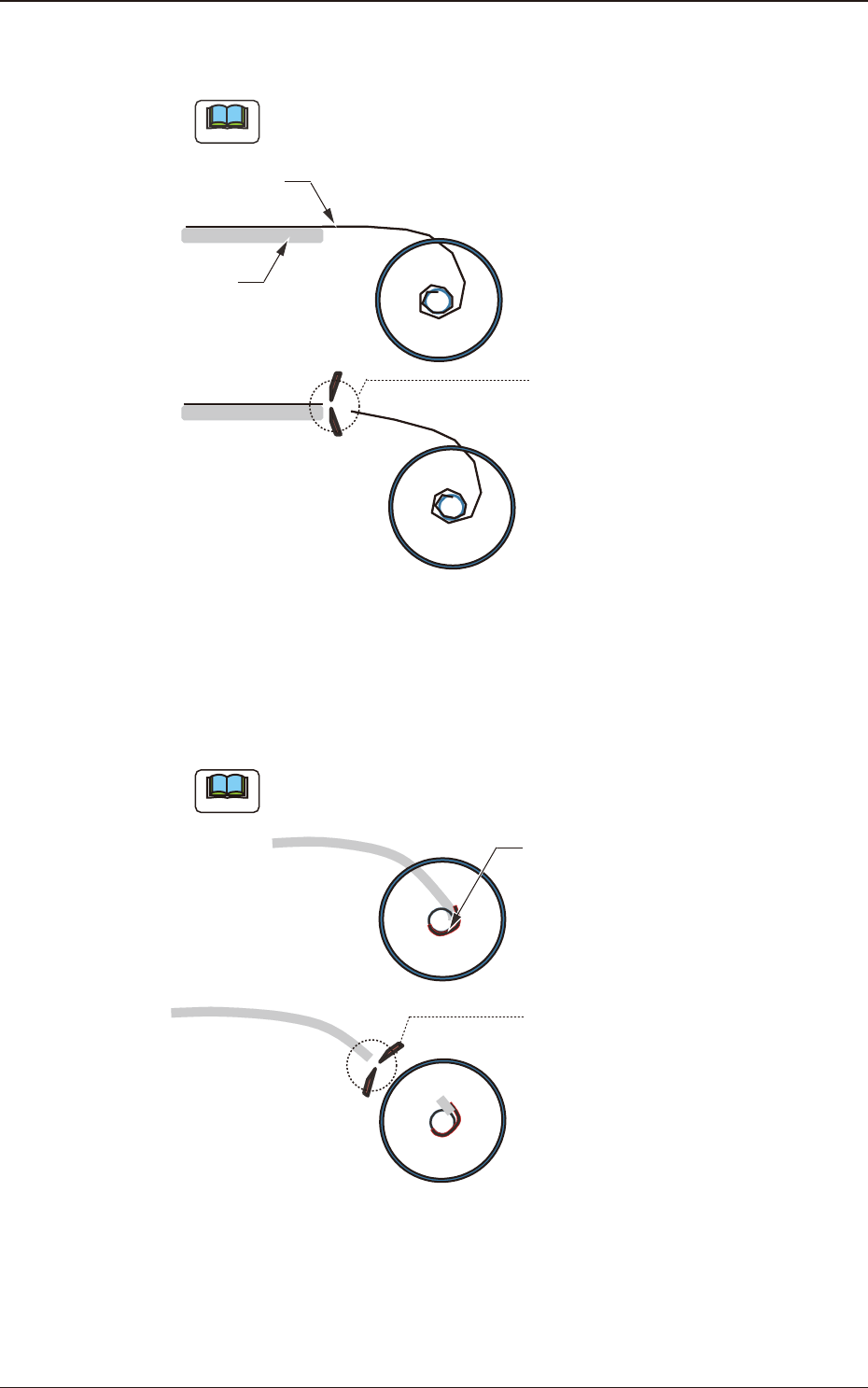
•
No Taping components where the cover tape at the tape end is longer than the
carrier tape end, can be applied.
Note
Cut the tape so that the end of the cover tape is in the same position as the
end of the carrier tape.
(It does not satisfy the
specifications in Item
7.1.2 in IEC60286-3
and JISC0806-3).
Cut
Cover
Tape
Carrier
Tape
Fig. A2
•
No taping components where the tape cannot be removed as it is because the
tape end has been xed onto the reel’s hub with adhesive tape, etc., can be
applied.
Note
Cut the tape end using scissors so that the adhesive tape is removed, and
remove the reel.
Cut
It has been attached
with adhesive tape.
(It does not satisfy the
specifications in Item
7.1.2 in IEC60286-3
and JISC0806-3).
Fig. A3
OM-1833
1-3