OM-1833-001w_SL.pdf - 第24页
1.2 Constraints 1504-001 • If the carrier tape meanders greatly , the loading operation might not be performed normally because of the tape contact in the tape route. Therefore, careful checking is required. F F Tape Gui…
1504-001
1.2 Constraints
•
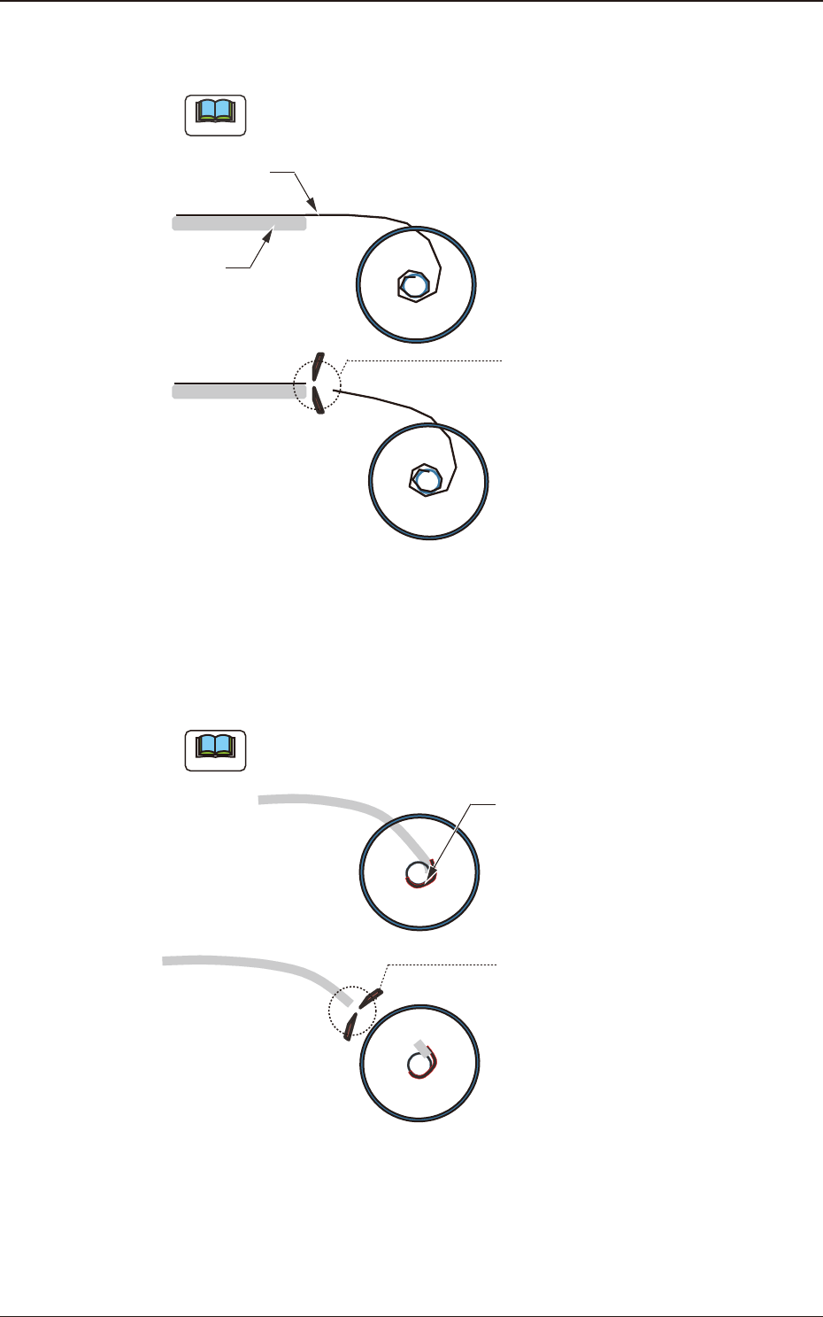
No Taping components where the cover tape at the tape end is longer than the
carrier tape end, can be applied.
Note
Cut the tape so that the end of the cover tape is in the same position as the
end of the carrier tape.
(It does not satisfy the
specifications in Item
7.1.2 in IEC60286-3
and JISC0806-3).
Cut
Cover
Tape
Carrier
Tape
Fig. A2
•
No taping components where the tape cannot be removed as it is because the
tape end has been xed onto the reel’s hub with adhesive tape, etc., can be
applied.
Note
Cut the tape end using scissors so that the adhesive tape is removed, and
remove the reel.
Cut
It has been attached
with adhesive tape.
(It does not satisfy the
specifications in Item
7.1.2 in IEC60286-3
and JISC0806-3).
Fig. A3
OM-1833
1-3
1.2 Constraints
1504-001
•
If the carrier tape meanders greatly, the loading operation might not be
performed normally because of the tape contact in the tape route. Therefore,
careful checking is required.
F
F
Tape Guide
Carrier Tape (Meandering)
Fig. A4
•
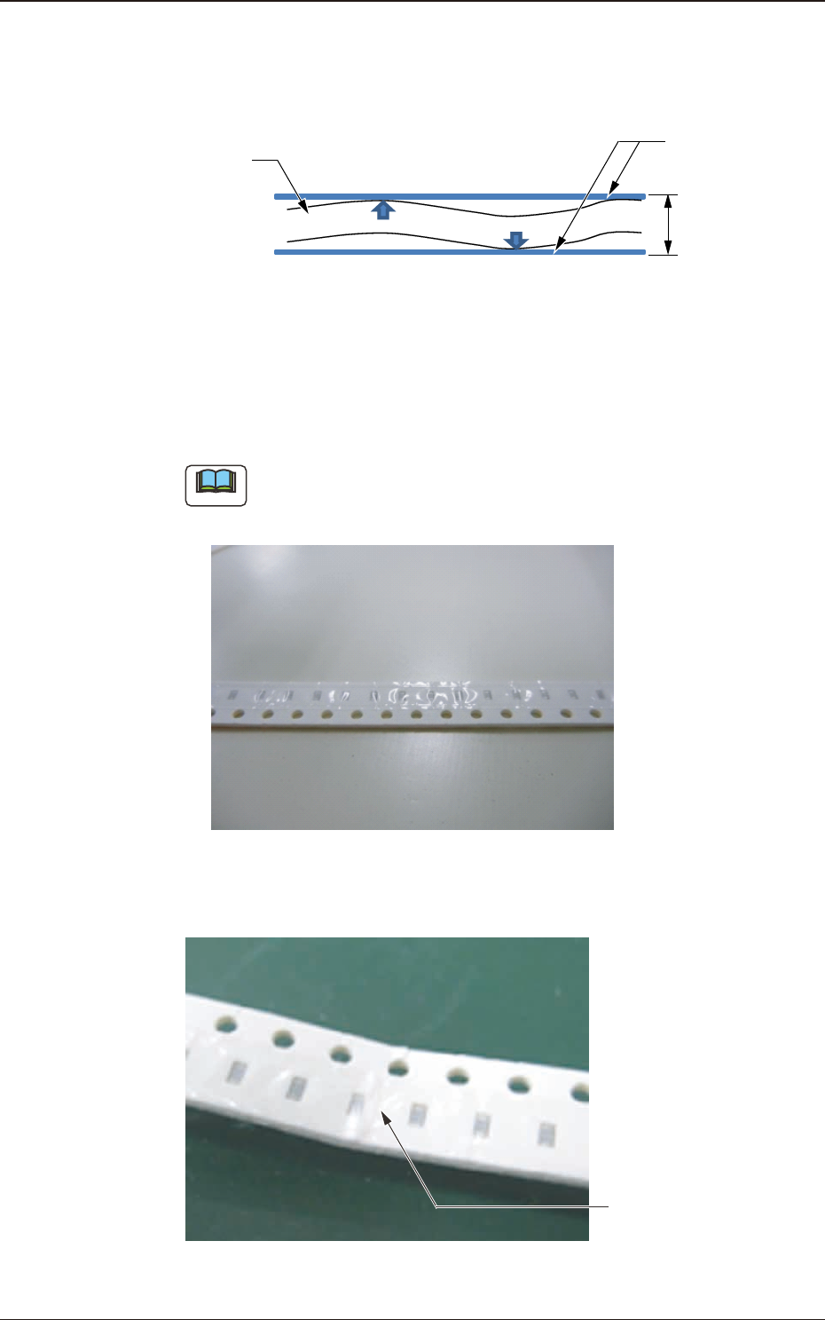
For the tape section where thick paper tape is used and bends signicantly, the
cover tape is waving at a position close to the reel core. In such cases, the cover
tape processing might not be performed correctly.
Note
It might improve when the tape feeding speed is reduced.
Fig. A5
•
For a creased tape, cover tape processing might not work
.
Crease
Fig. A6
OM-1833
1-4

1.2 Constraints
•
For components that use strong adhesive tape, checking them is required.
•
Tape where a foreign substance such as a small piece of splicing tape, has been
attached to the cover tape, cannot be used.
For component reloading, the procedure specially designed for the SL tape
feeder is used. The splicing operation is not available.
•
Components to be loaded on the SL tape feeder are different from those on the
existing tape feeder. Therefore, the component position arrangement might
need to be changed.
When the component position arrangement is changed, optimize the pattern
program.
1504-001
OM-1833
1-5