OM-1833-001w_SL.pdf - 第28页
1504-001 1.3 T aping Specications • The top surface of any component in T aping Components should be lower than the top surface of the carrier tape keeping proper pocket clearance of the carrier tape. MIN. 40μm MIN. 40μ…
1.3 Taping Specications
1504-001
Appropriate taping
•
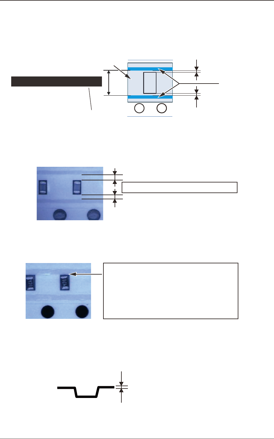
The fused bands of the cover tape in Taping Components should not interfere
with any pockets, and they should be along the pockets without deviation or
meandering.
Cover tape
Distance between fused bands
Inner dimension
excluding the fused bands
0.1mm or more
0.1mm or more
Fused bands
Fig. A7
Example of applicable Taping Components
The clearance should be 0.1 mm or more.
Fig. A8
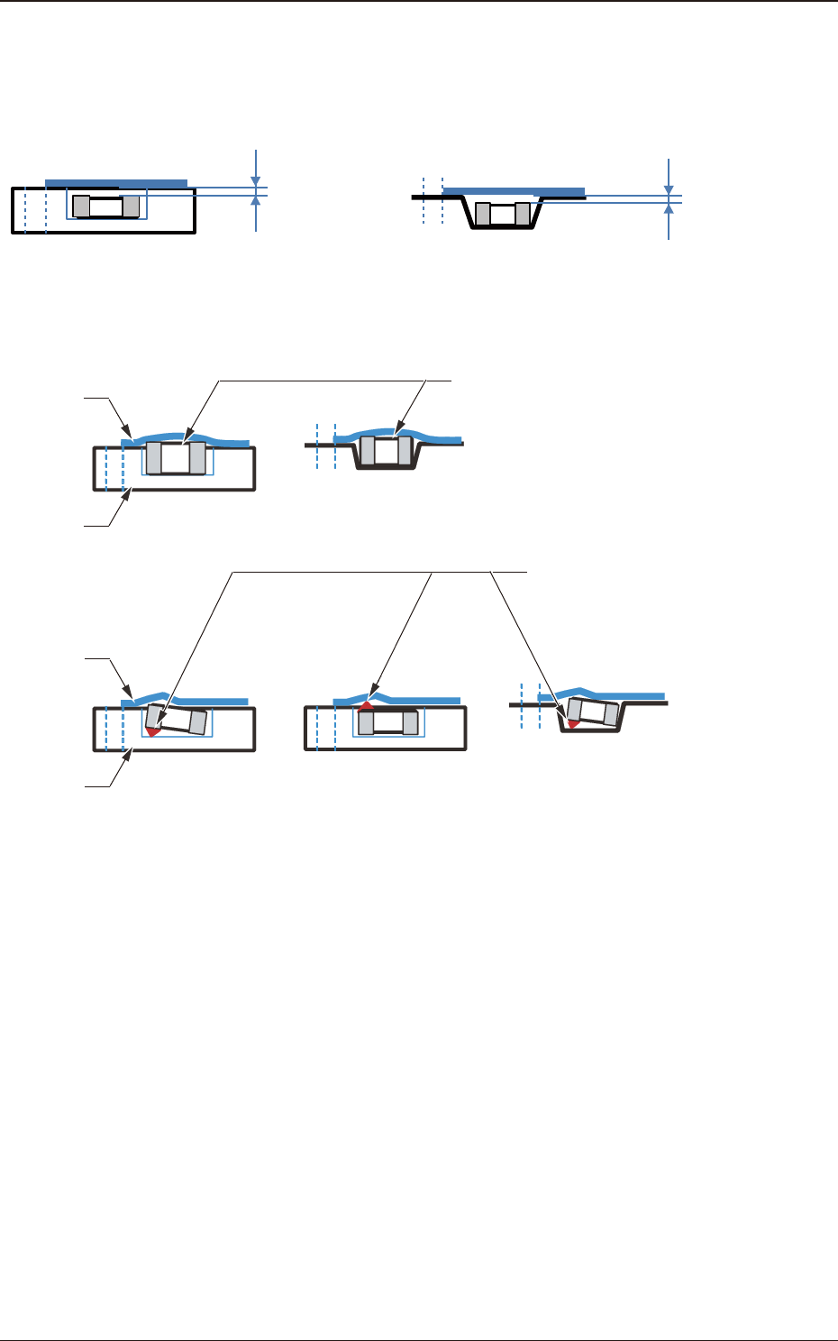
* Taping Components like the followings can not be dealed with the SL feeders.
ⅰ) The fused band is interfered with the pockets.
ⅱ) The fused bands are deviated to the center of the
pockets.
ⅲ) For the embossed Taping Components with fused
bands close to the pockets and a weak body of
the carrier tape, it is necessary to test it because
its cover tape processing will not be done
normally.
Fig. A9
•
The thickness of the carrier tape in Taping Components should be 0.16 mm or
more and it should be 0.3 mm or less.
0.16 mm ≤ t ≤
0.30 mm
Fig.A 10
OM-1833
1-7
1504-001
1.3 Taping Specications
•
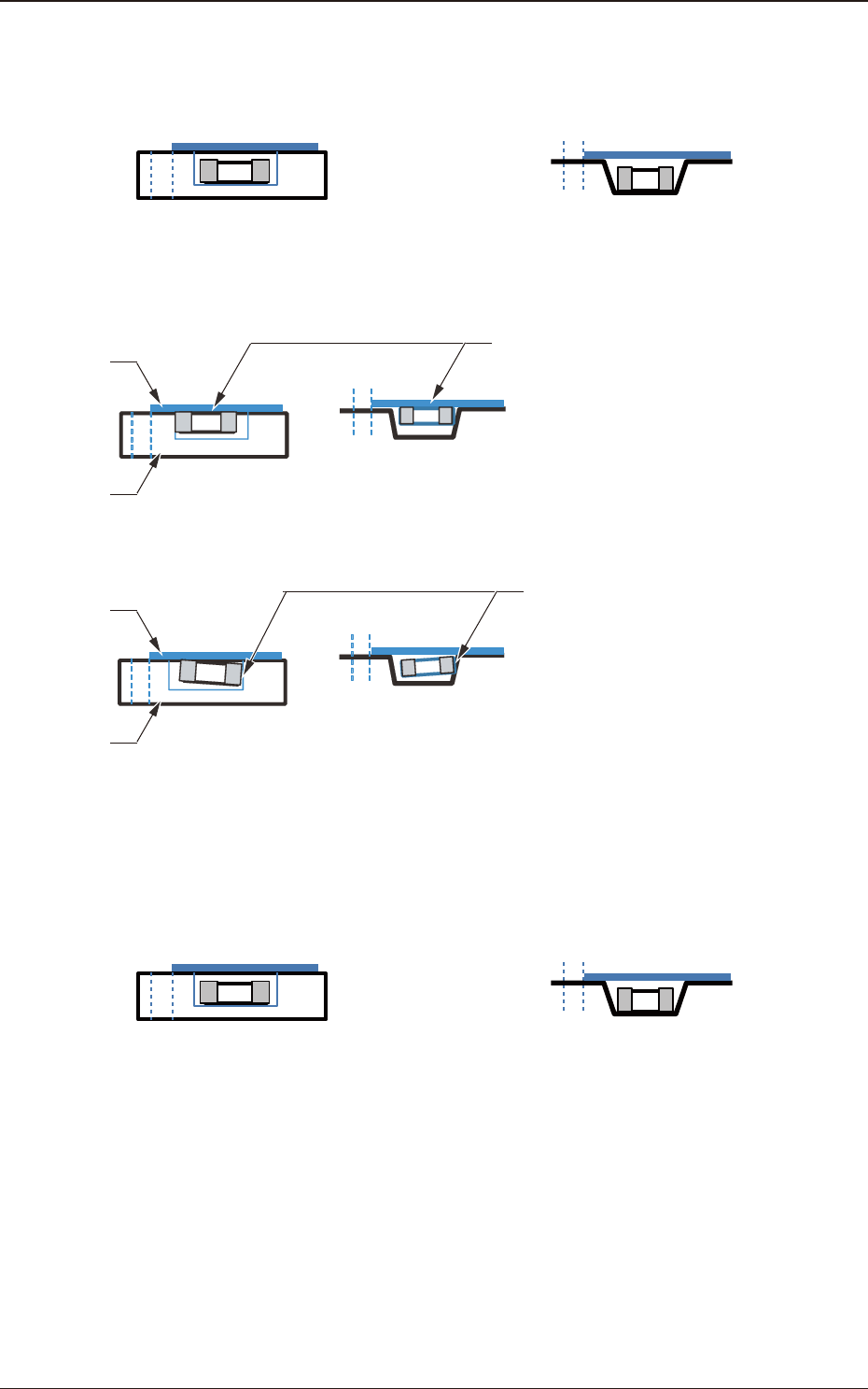
The top surface of any component in Taping Components should be lower than
the top surface of the carrier tape keeping proper pocket clearance of the carrier
tape.
MIN. 40μm
MIN. 40μm
Paper tape Embossed tape
Fig. A11
* Taping Components like the followings can not be dealed with the SL feeders.
The component is projected out from
the carrier tape.
(The paragraphs 3.1/3.2 of IEC 60286-3
(JIS C0806-3) are not satisfied.)
Paper tape Embossed tape
Cover tape
Carrier tape
Paper tape
Embossed tape
Cover tape
Carrier tape
The rising like a bump is adhered to
the electrode.
→
So, the component is projected
out from the carrier tape.
(The paragraphs 3.1/3.2 of IEC 60286-3
(JIS C0806-3) are not satisfied.)
Fig. A12
OM-1833
1-8
•
Taping Components should not have any component being adhered to the
carrier tape or the cover tape.
Paper tape Embosses tape
Fig. A13
* Taping Components like the followings can not be dealed with the SL feeders.
The component is being
adhered to the cover tape.
(The paragraph 5.2.3 of IEC 60286-3
(JIS C0806-3) is not satisfied.)
Paper tape Embossed tape
Cover tape
Carrier tape
The component is being adhered
to the side wall of the carrier tape pocket.
The paragraph 5.2.3 of IEC 60286-3
(JIS C0806-3) is not satisfied.)
Paper tape Embossed tape
Cover tape
Carrier tape
Fig. A14
•
The cover tape of Taping Components should not concave downward into
pockets, and it should be fused on the carrier tape in at manner.
Paper tape Embosses tape
Fig. A15
1.3 Taping Specications
OM-1833
1-9