OM-1833-001w_SL.pdf - 第32页
1.4 T ypes T ape Feeders T able A3 T ape Feeder T ape Width × Feed Pitch (mm) Cover T ape Processing Section T ype T ypes of T ape Mass (kg) Power Supply Barcode Label Color SL-48085 8 mm Dual T ape Feeder (Note) 8 × 1, …
•
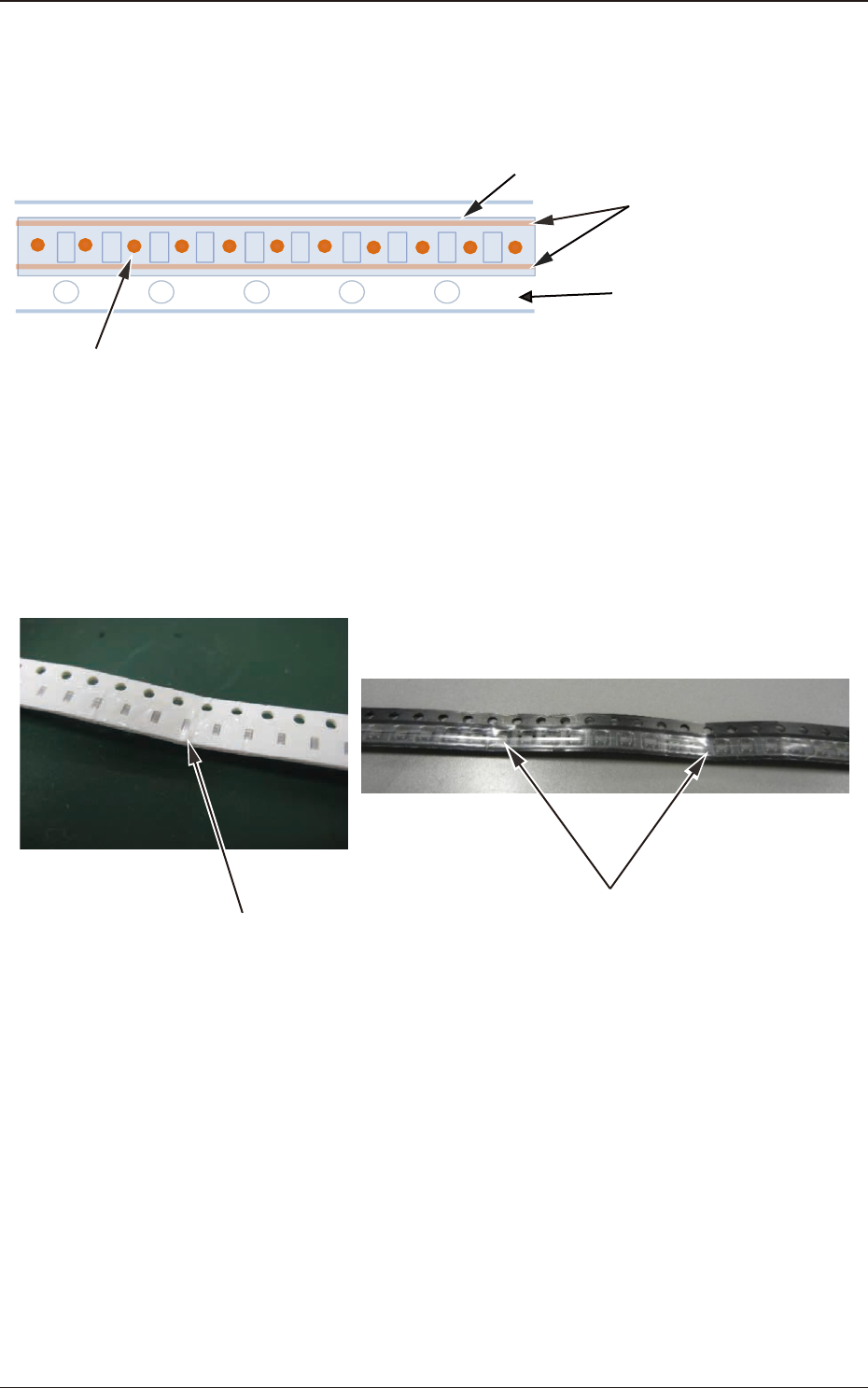
For the Taping Components, fused bands of the cover tape should be formed
only on the left and right of pockets' outside.
* Taping Components like the following can not be dealed with the SL feeders.
Cover tape
Fused hands of cover tape
Carrier tape
Other than left and right of pockets' outside, fused spots exist on the surface of between pockets.
(Also, any Taping Components with fused spots in non-periodical manner can not be dealed with the SL feeders.)
Fig. A20
•
Taping components should not have any creased part on the carrier tape.
* For Taping Components with any creased portion like the followings, the cover
tape processing might not work normally.
Creased parts
Creased parts
Fig. A21
1.3 Taping Specications
OM-1833
1-11
1.4 Types Tape Feeders
Table A3
Tape Feeder
Tape Width ×
Feed Pitch (mm)
Cover Tape
Processing
Section Type
Types of
Tape
Mass
(kg)
Power Supply
Barcode
Label Color
SL-48085
8 mm Dual
Tape Feeder
(Note)
8 × 1, 2 S
Paper
Embossed
3.5 DC24V
±
10% Blue + White
SL-48086
8 mm Dual
Tape Feeder
8 × 2, 4 M
Paper
Embossed
3.5 DC24V
±
10% Yellow + White
SL-48087
8 mm Dual
Tape Feeder
8 × 2, 4 L
Paper
Embossed
3.5 DC24V
±
10% Pink + White
SL-48088
8 mm Dual
Tape Feeder
8 × 4 LL
Paper
Embossed
3.5 DC24V
±
10% White
Note
SL-48085 is applicable to 1 mm pitch tape.
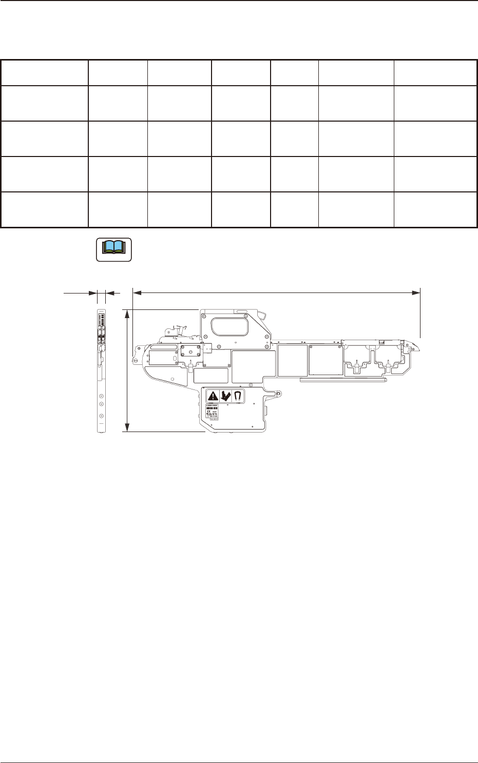
732
312
20.2
Unit : mm
Fig. A12 8 mm Dual Tape Feeder
1504-001
1.4 Types Tape Feeders
OM-1833
1-12
1504-001
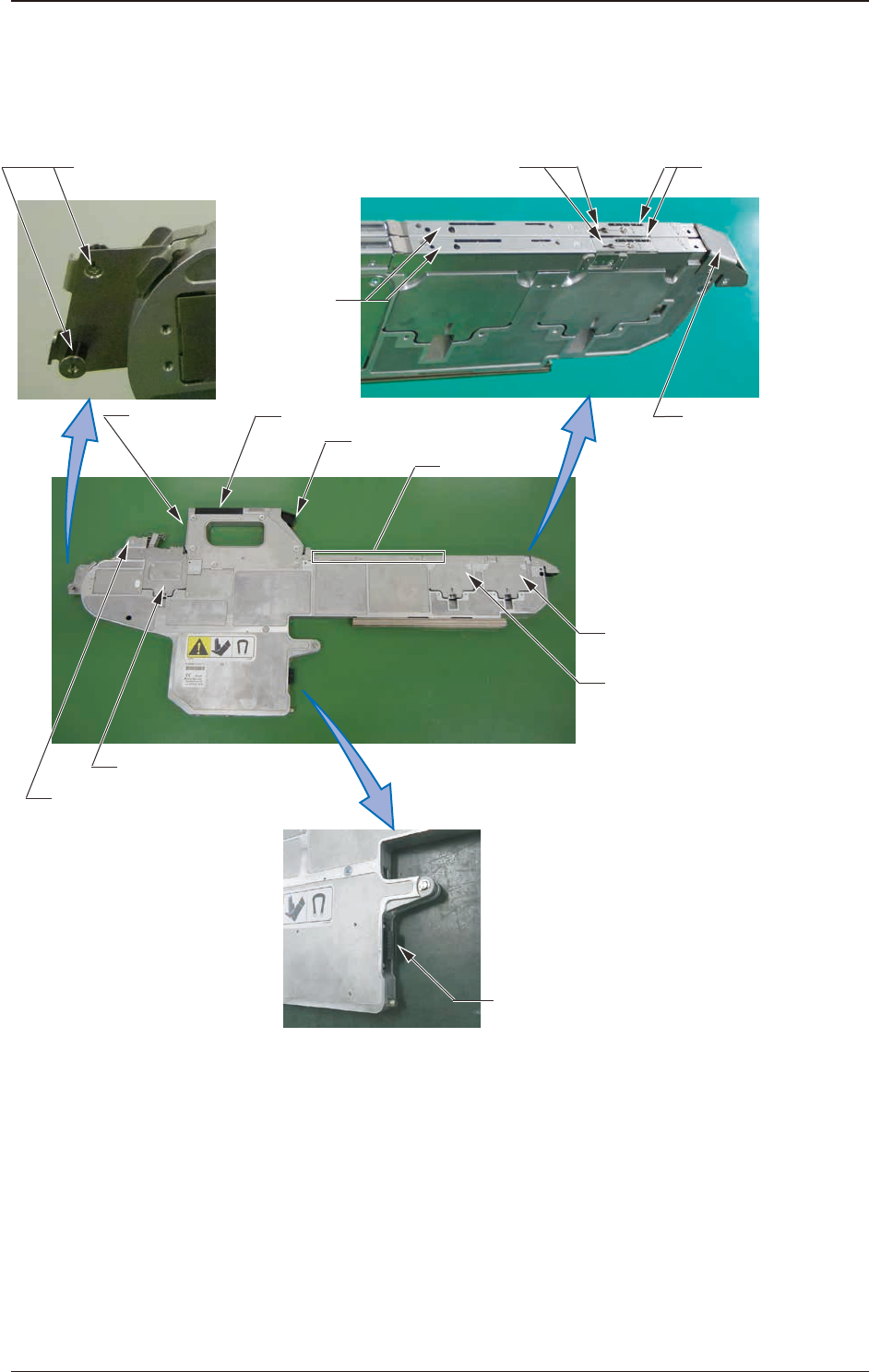
1.5 Name and Function of Each Section
It is described in SL-48085 (8 mm Dual Tape Feeder)
[1] Operation Panel
[3] Clamp Release Lever
[5] Chute
[7] Sprocket (2)
[6] Sprocket (1)
[14] Connector
[13] Tape Outlet Guide
(At the succeeding tape set-up)
[9] Suppressor
[10] Cover Tape
Processing Section
[12] Tape Outlet Guide
[11] Component
Pick-up Section
[2] Barcode
Label
[4] Loading Suppressor
[8] Sprocket (3)
Fig. A23
1.5 Name and Function of Each Section
OM-1833
1-13