OM-1833-001w_SL.pdf - 第38页
1504-001 2. Attachment and Detachment of T ape Notice In the case that a pocket is cut when the tape is cut off at a specied position, cut the tape so that the pocket is not cut. Also, do not cut the tape at a position …
1504-001
2. Attachment and Detachment of Tape
2. Attachment and Detachment of Tape
Table End Cutting Position
Table End Cutting Position
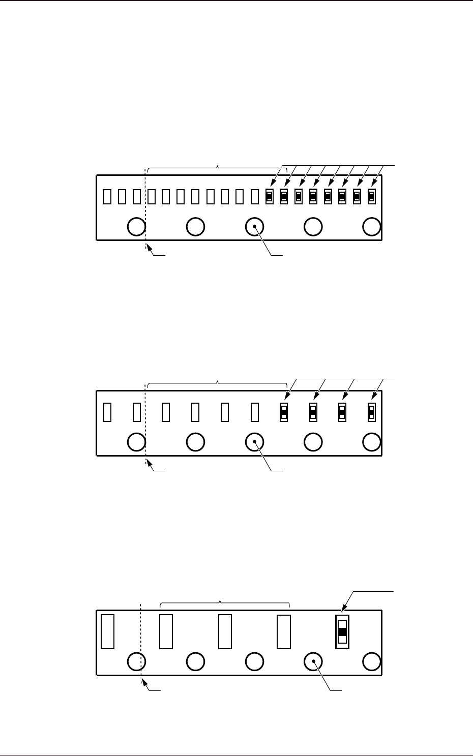
•
For Tape Width: 8 mm, Feed Pitch: 1 mm
Cut the tape at the back end of the third perforation from the one ahead of the
last pocket where a component has been put.
Pockets where a
component has
been put
123
Cutting Position
(Back end of the perforation)
Perforation ahead of the
last pocket where a component has been put
No. of Empty Pockets: 8 to 10
Fig. B1
•
For Tape Width: 8 mm, Feed Pitch: 2 mm
Cut the tape at the back end of the third perforation from the one ahead of the
last pocket where a component has been put.
Pockets where a
component has
been put
123
Cutting Position
(Back end of the perforation)
Perforation ahead of the
last pocket where acomponent has been put
No. of Empty Pockets: 4 to 5
Fig. B2
•
For Tape Width: 8 mm, Feed Pitch: 4 mm
Cut the tape at the position of 1/4 of the fourth perforation from the one ahead
of the last pocket where a component has been put.
Pockets where a
component has
been put
123
Cutting Position
(1/4 position of the perforation)
Perforation ahead of thelast
pocket where a component has
been put
No. of Empty Pockets: 3
4
Fig. B3
OM-1833
2-1
1504-001
2. Attachment and Detachment of Tape
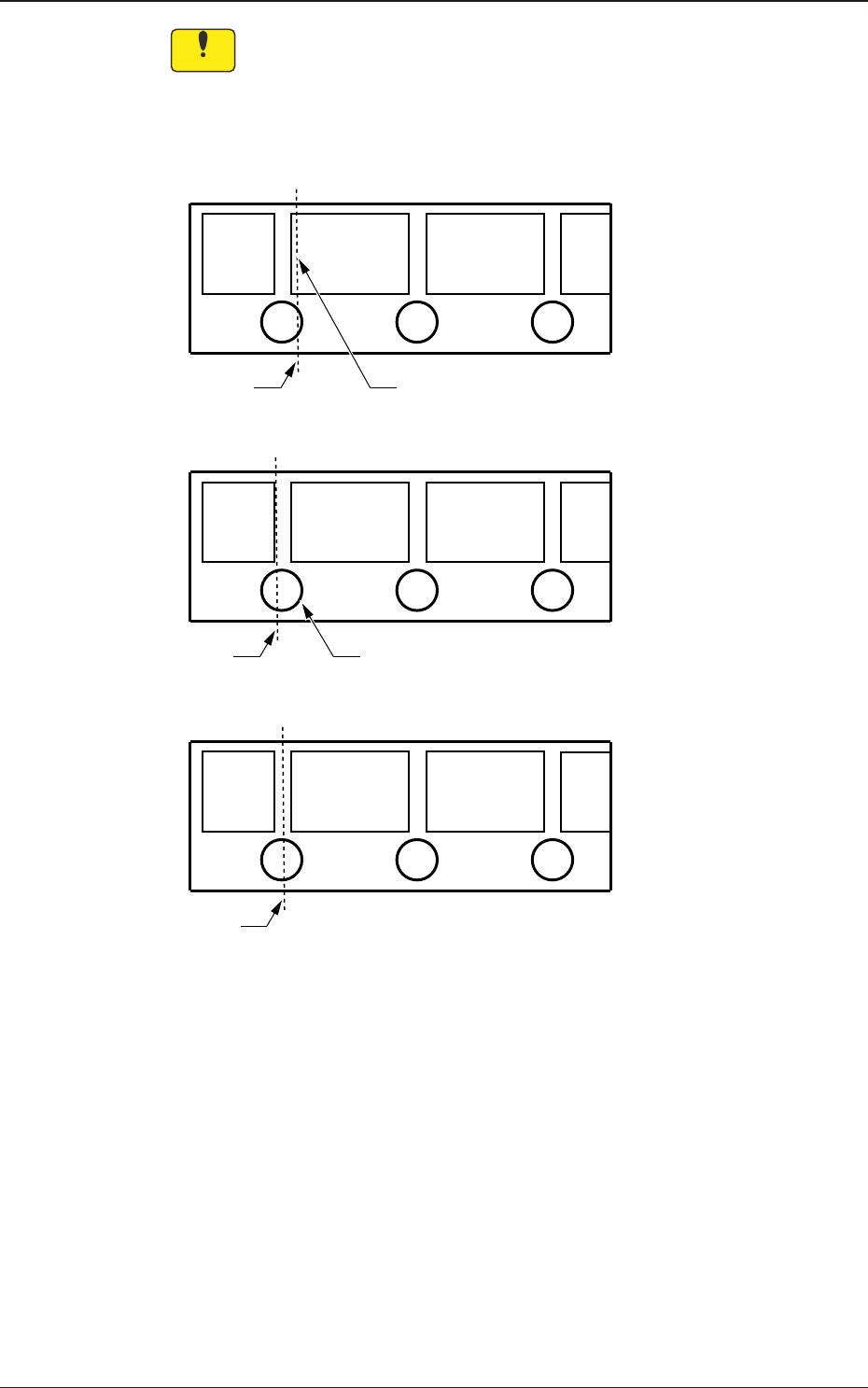
Notice
In the case that a pocket is cut when the tape is cut off at a specied
position, cut the tape so that the pocket is not cut. Also, do not cut the
tape at a position where more than half of a perforation is left. When the
tape is cut off where the pocket is cut, or more than half of a perforation
is left, it might cause a malfunction.
Cutting
Position
The pocket is cut.
NG
OK
Cutting
Position
More than half of a perforation is left.
NG
Cutting
Position
Fig. B4
OM-1833
2-2
2.1 Tape Attachment Procedure
1504-001
2.1 Tape Attachment Procedure
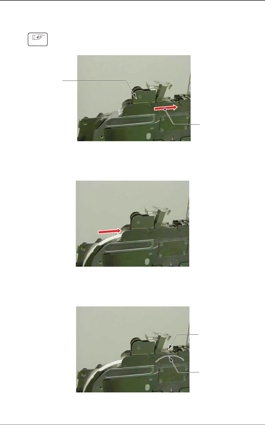
Procedure
(1) Slide the loading suppressor forward on the lane where the tape is to be set
up to prepare for tape insertion.
Loading
Suppressor
Slide it forward.
Fig. B5
(2) Insert the tape.
Fig. B6
(3) Insert the tape so that the end of the tape contacts the sprocket (3) gear.
Insert the
tape end to
this position.
Sprocket(3)
Fig. B7
OM-1833
2-3