OM-1833-001w_SL.pdf - 第41页
1504-001 2.2 T ape Removal Procedure 2.2 T ape Removal Procedure Procedure (1) Slide the loading suppressor to this side on the lane where the tape is to be removed, and widen the tape insertion opening. Loading Suppress…
1504-001
2.1 Tape Attachment Procedure
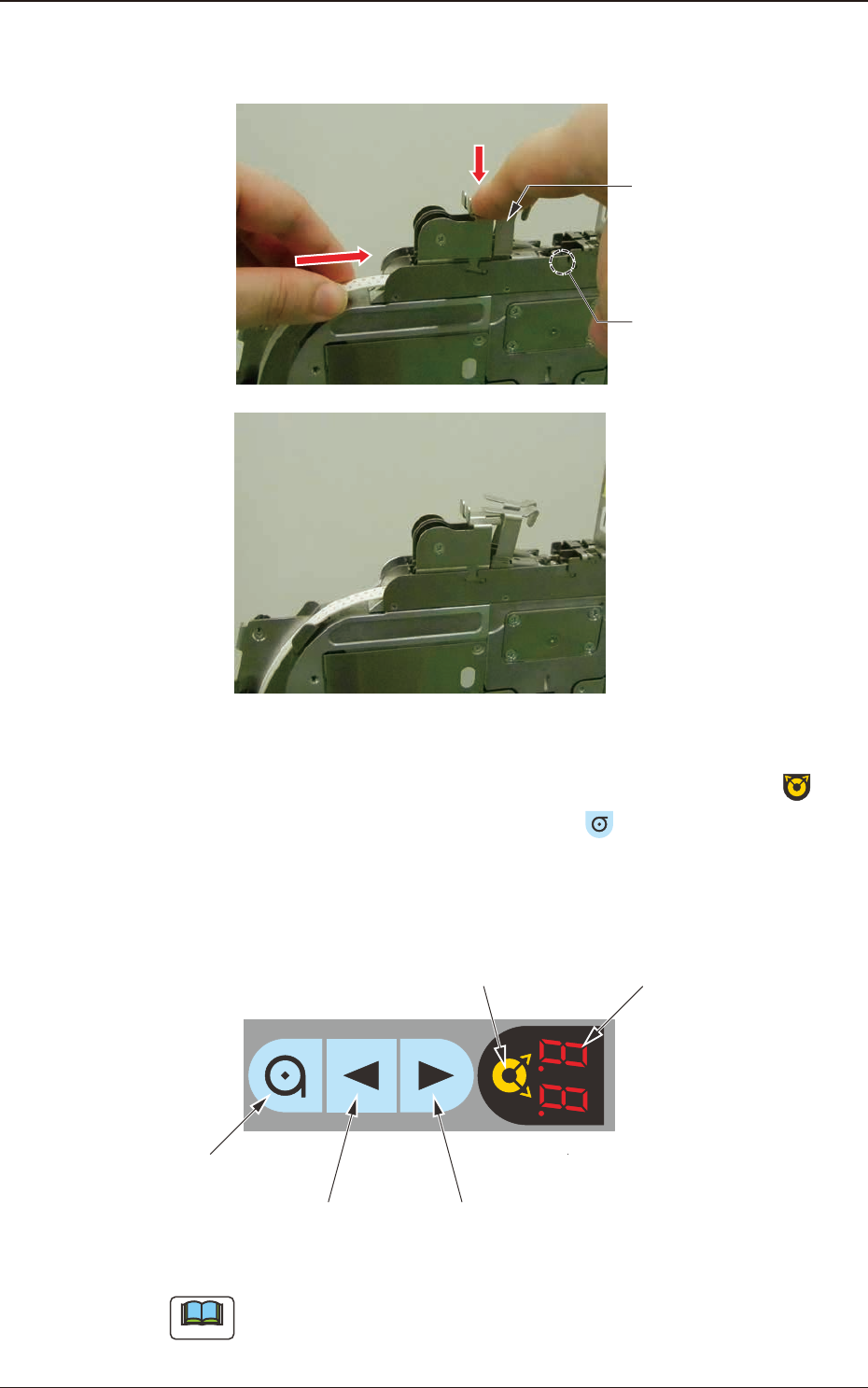
(4) Push down the lever to lift the roller and insert the tape about 10mm, so that
the tape is engaged with the sprocket (3) gear.
Tape setup completed
Roller
Lever
Fig. B8
(5) Perform the tape loading operation. After selecting the lane using the
button on the operation panel, hold down the
button for one second.
(After 1-second pressing and holding-down operation of the button is
detected, the tape loading operation starts and the tape is carried in the
component pick-up position automatically.)
Digital IndicatorLane Selection Button
Forward ButtonBackward Button
Take-up Button
Fig. B9
Note
Start-up Conditions:
The tape detection sensor (2) should be turned ON.
The tape has not been set up.
OM-1833
2-4
1504-001
2.2 Tape Removal Procedure
2.2 Tape Removal Procedure
Procedure
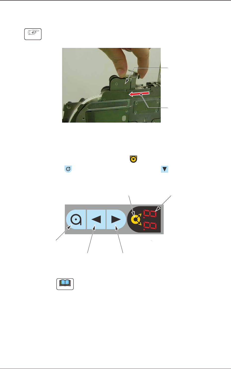
(1) Slide the loading suppressor to this side on the lane where the tape is to be
removed, and widen the tape insertion opening.
Loading
Suppressor
Slide it to this side.
Fig. B10
(2) Perform the tape unloading operation.
After selecting the lane using the
button on the operation panel, press
the
button and within one second, press the button. (The tape will
reverse backward).
Digital IndicatorLane Selection Button
Forward ButtonBackward Button
Take-up Button
Fig. B11
Note
Start-up Conditions:
The tape detection sensor (1) is turned ON and the tape has been setup, or
the tape detection sensor (2) is turned OFF and the tape has been setup.
OM-1833
2-5
1504-001
2.2 Tape Removal Procedure
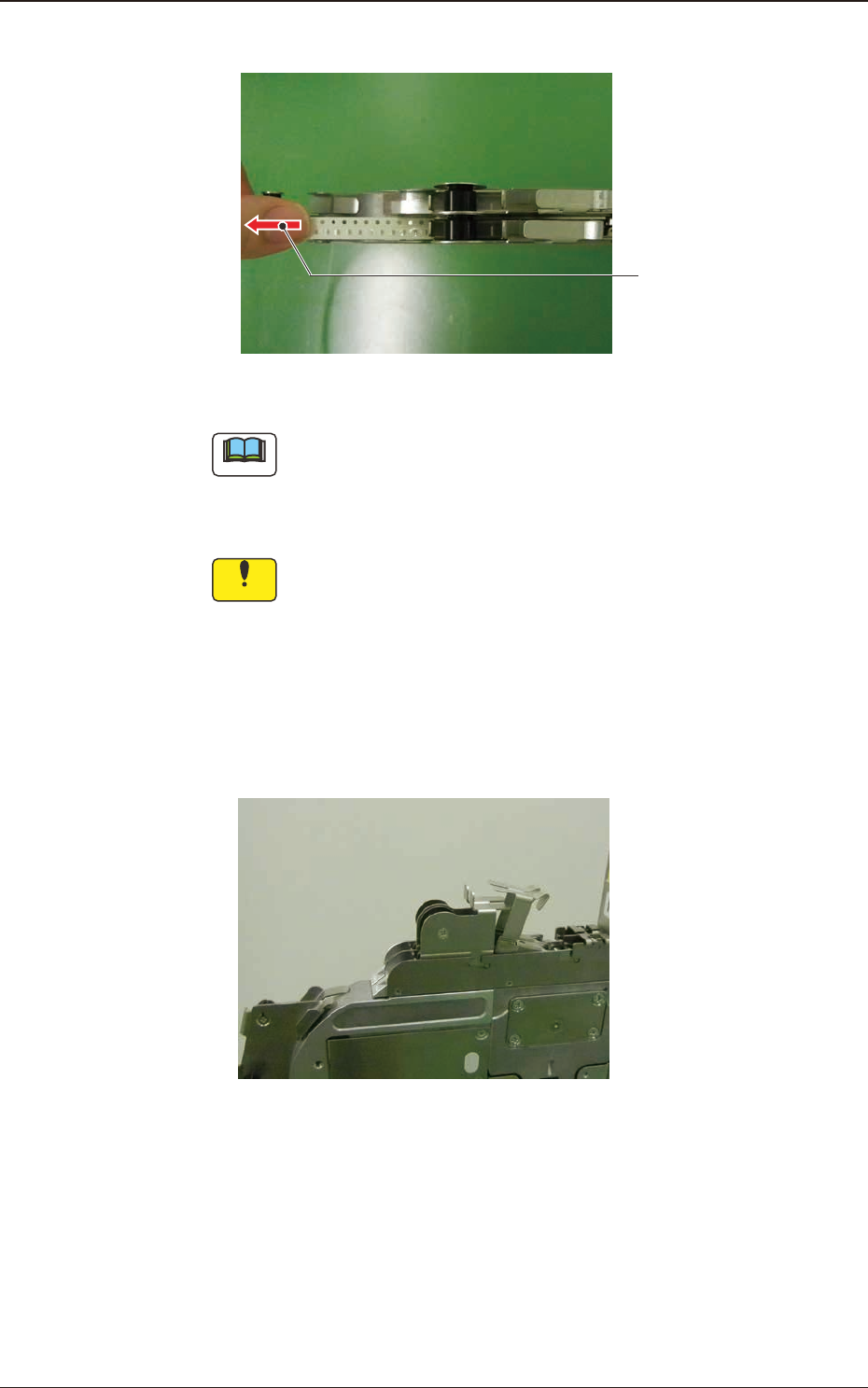
(3) Draw the tape out slowly to this side by hand during the unloading operation.
Pull it out slowly.
Fig. B12
Note
Because sufcient reverse rotation time of the tape feeding motor (servo-
motor) is secured to enable the tape collection, pressing any operation
switch button can complete the unloading operation after the tape has been
collected.
Notice
When the teeth of sprocket (1) and sprocket (2) are engaged with
the perforations on the tape, do not pull the tape forcibly.
Doing so might deform the perforations and the tape cannot be
setup in the correct feeding position when the tape is attached
again.
(4) When the tape removal operation has been completed, slide the loading
suppressor forward to return it to the specied position.
Tape setup completed
Fig. B13
OM-1833
2-6