OM-1833-001w_SL.pdf - 第44页
1504-001 2.3 Component Reload T ape Attachment Procedure Change the route of the preceding tape to the upper side. Fig. B17 (4) Insert the succeeding component reload tape. Fig. B18 (5) Insert it to a position so that th…
1504-001
2.3 Component Reload Tape Attachment Procedure
2.3 Component Reload Tape Attachment Procedure
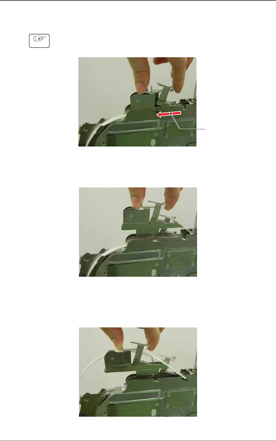
Procedure
(1) Slide the loading suppressor to this side on the lane where the component
reload tape is to be set up.
Slide it to this side.
Fig. B14
(2) Lift the loading suppressor to remove it.
Fig. B15
(3) Set the preceding tape on the loading suppressor and change the route of the
preceding tape to the upper side.
Fig. B16
OM-1833
2-7
1504-001
2.3 Component Reload Tape Attachment Procedure
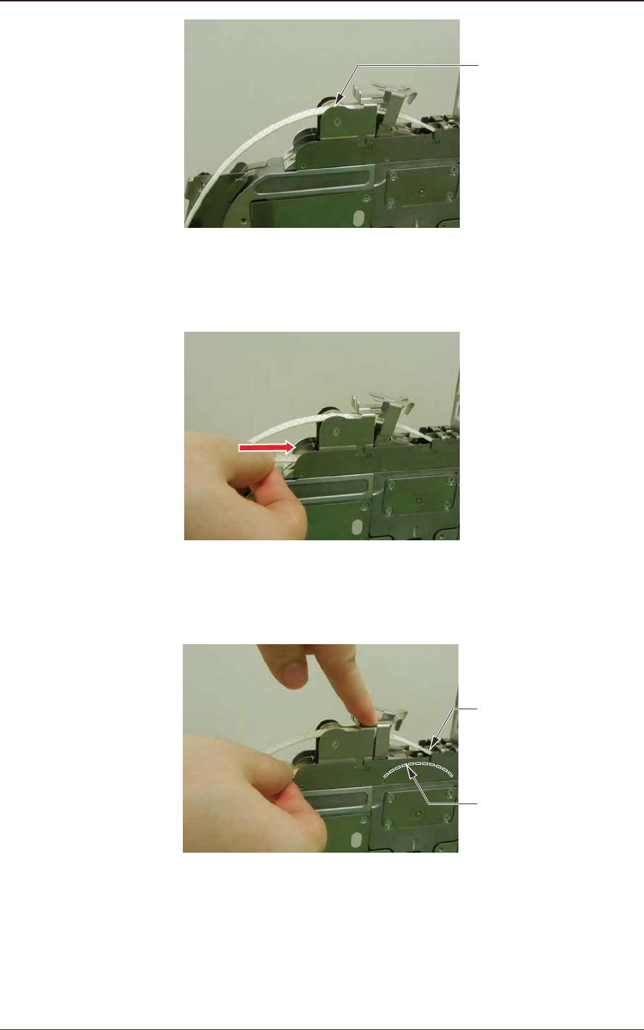
Change the route
of the preceding
tape to the upper side.
Fig. B17
(4) Insert the succeeding component reload tape.
Fig. B18
(5) Insert it to a position so that the tape end contacts the sprocket (3) gear.
Insert the tape end
to this position.
Sprocket (3)
Fig. B19
OM-1833
2-8
1504-001
2.3 Component Reload Tape Attachment Procedure
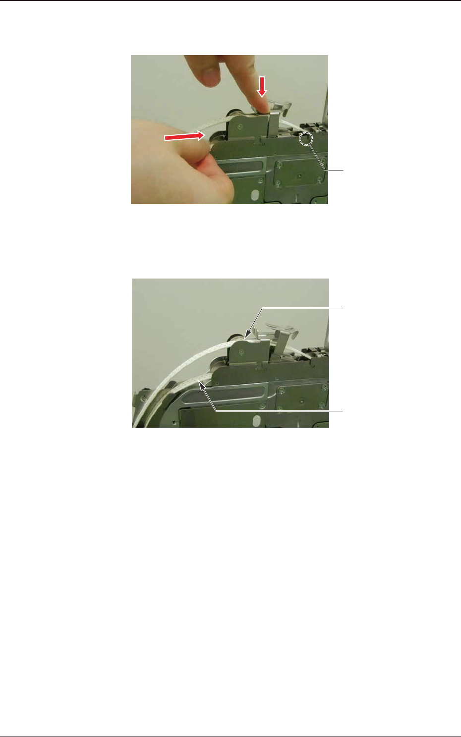
(6) Press down the lever to lift the roller and insert the tape about 10mm, so that
the tape is engaged with the sprocket (3) gear.
Roller
Fig. B20
(7) Then, the setup of the succeeding component reload tape is completed.
Preceding Tape
Succeeding Componet
Reload Tape
Fig. B21
OM-1833
2-9