OM-1833-001w_SL.pdf - 第66页
4.2.12 I/O Status Indication for Sensor , etc. This function uses seven-segment indicator as the status indicator for the sensor attached to the feeder. Procedure (1) Press the button and within 2 seconds, press the butt…
4.2.10 Forcible Feeding Operation
This function feeds forward the loaded tape forcibly.
In the condition that the tape end is in the feeder, with an empty pocket zone at the
tape end section, the tape is fed forward forcibly at high-speed.
Procedure
(1) Press the button to select the lane.
(2) Press the
button and while holding it down, press the button within 2
seconds. Hold down both buttons simultaneously for one second.
Note
(a) Startup Conditions:
The tape detection sensor (1) has been turned OFF.
The tape has not setup and the tape end detection is in the latch
condition.
What is the tape end detection (latch)?
The tape detection sensor (1) has been turned OFF when the tape
feeding operation is performed.
In the case that the conditions where that tape has not been setup,
continue (Even when the total feeding amount reaches 20mm, the
tape has not been setup during such time) the tape end detection (latch
memory) is turned ON, assuming that the tape end section has been
inserted into the feeder.
•
This memory is cleared in any of the following cases.
The forcible feeding operation is ended normally.
•
The remaining tape has been removed and both tape detection
sensors (1) and (2) do not detect any tape.
(b) During the operation, pressing any operation switch button stops the
forcible feeding operation.
4.2.11 Tape Feeding Deceleration Setup Clear
When the tape feeder speed deceleration has been set on the component library
data, the corresponding lane dot display
ashes, which disables the feeder
pitch setup operation.
In order to return to the normal condition, clearing the feeding acceleration setting
is required.
Procedure
(1) Press the button to select the lane.
(2) Press and hold the
button and within 2 seconds, press the button.
Hold both buttons simultaneously for two seconds.
After it has been conrmed that the button has been held down for 2 seconds,
the ashing dot display
changes to a continuously illuminating display,
which enables the feeding pitch setup operation.
1504-001
4.2 Operation of Operation Panel
OM-1833
4-9
4.2.12 I/O Status Indication for Sensor, etc.
This function uses seven-segment indicator as the status indicator for the sensor
attached to the feeder.
Procedure
(1) Press the button and within 2 seconds, press the button and keep this
condition (two buttons are being pressed) for 2 seconds.
When it has been conrmed that the button has been held down for 2
seconds, this mode is transferred to the I/O display mode.
Note
When this mode is to be ended, the normal display mode returns with
the procedure for the feeder power shutdown or transfer operation of this
mode.
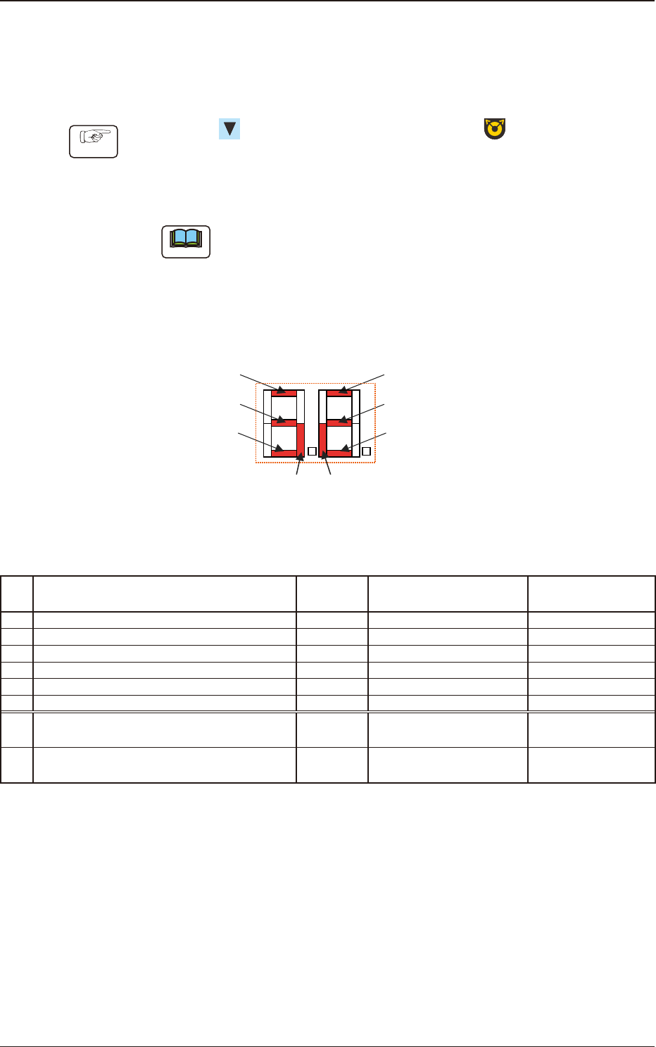
The items corresponding to each of the seven segments and I/O (Sensor and
Signal) are as follows.
Seven Segments
[1]
[7] [8]
[2]
[3]
[4]
[5]
[6]
Fig. D2
Table D1
No. Sensor/Signal Name Lighting Status
Work Presence/
Absence
1 Lane #1 Tape Detection Sensor (1) ON (Low) Light Shielded Present
2 Lane #1 Tape Detection Sensor (2) ON (Low) Light Shielded Absent
3 Lane 1 Sprocket Home Position Detection Sensor ON (Low) Magnetic Pole Detection -
4 Lane #2 Tape Detection Sensor (1) ON (Low) Light Shielded Present
5 Lane #2 Tape Detection Sensor (2) ON (Low) Light Shielded Absent
6 Lane 2 Sprocket Home Position Detection Sensor ON (Low) Magnetic Pole Detection -
7
Connection Conrmation Signal
(Output Signal to the Mounter Main Machine)
ON (Low) ON (Low) -
8
READY Signal
(Output Signal to the Mounter Main Machine)
ON (Low) ON (Low) -
1504-001
4.2 Operation of Operation Panel
OM-1833
4-10
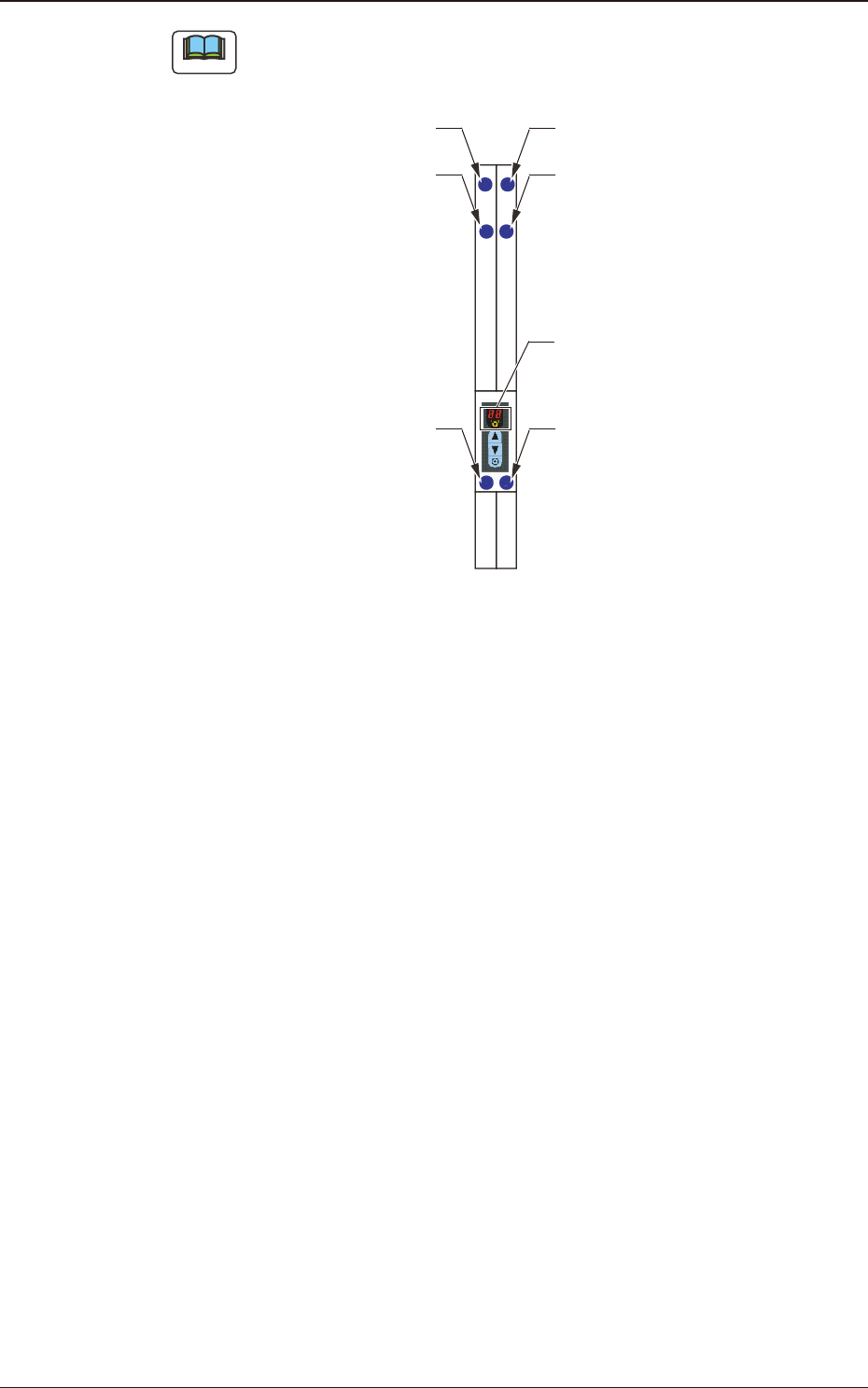
Note
The layout of the seven segments in the display section is arranged as the order
of the sensor arrangement on the feeder.
Lane 1 Sprocket Home Position
Detection Sensor
Lane #1 Tape Detection Sensor (2)
Lane #1 Tape
Detection Sensor (1)
Lane 2 Sprocket Home Position
Detection Sensor
Lane #2 Tape Detection Sensor (2)
Lane #2 Tape
Detection Sensor (1)
Seven Segments
Fig. D3
1504-001
4.2 Operation of Operation Panel
OM-1833
4-11