OM-1833-001w_SL.pdf - 第67页
Note The layout of the seven segments in the display section is arranged as the order of the sensor arrangement on the feeder . Lane 1 Sprocket Home Position Detection Sensor Lane #1 Tape Detection Sensor (2) Lane #1 Tap…
4.2.12 I/O Status Indication for Sensor, etc.
This function uses seven-segment indicator as the status indicator for the sensor
attached to the feeder.
Procedure
(1) Press the button and within 2 seconds, press the button and keep this
condition (two buttons are being pressed) for 2 seconds.
When it has been conrmed that the button has been held down for 2
seconds, this mode is transferred to the I/O display mode.
Note
When this mode is to be ended, the normal display mode returns with
the procedure for the feeder power shutdown or transfer operation of this
mode.
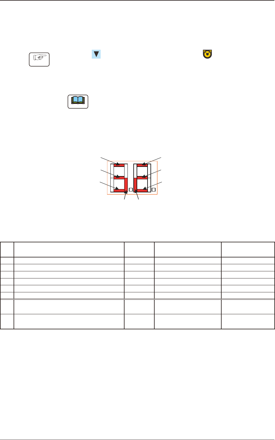
The items corresponding to each of the seven segments and I/O (Sensor and
Signal) are as follows.
Seven Segments
[1]
[7] [8]
[2]
[3]
[4]
[5]
[6]
Fig. D2
Table D1
No. Sensor/Signal Name Lighting Status
Work Presence/
Absence
1 Lane #1 Tape Detection Sensor (1) ON (Low) Light Shielded Present
2 Lane #1 Tape Detection Sensor (2) ON (Low) Light Shielded Absent
3 Lane 1 Sprocket Home Position Detection Sensor ON (Low) Magnetic Pole Detection -
4 Lane #2 Tape Detection Sensor (1) ON (Low) Light Shielded Present
5 Lane #2 Tape Detection Sensor (2) ON (Low) Light Shielded Absent
6 Lane 2 Sprocket Home Position Detection Sensor ON (Low) Magnetic Pole Detection -
7
Connection Conrmation Signal
(Output Signal to the Mounter Main Machine)
ON (Low) ON (Low) -
8
READY Signal
(Output Signal to the Mounter Main Machine)
ON (Low) ON (Low) -
1504-001
4.2 Operation of Operation Panel
OM-1833
4-10
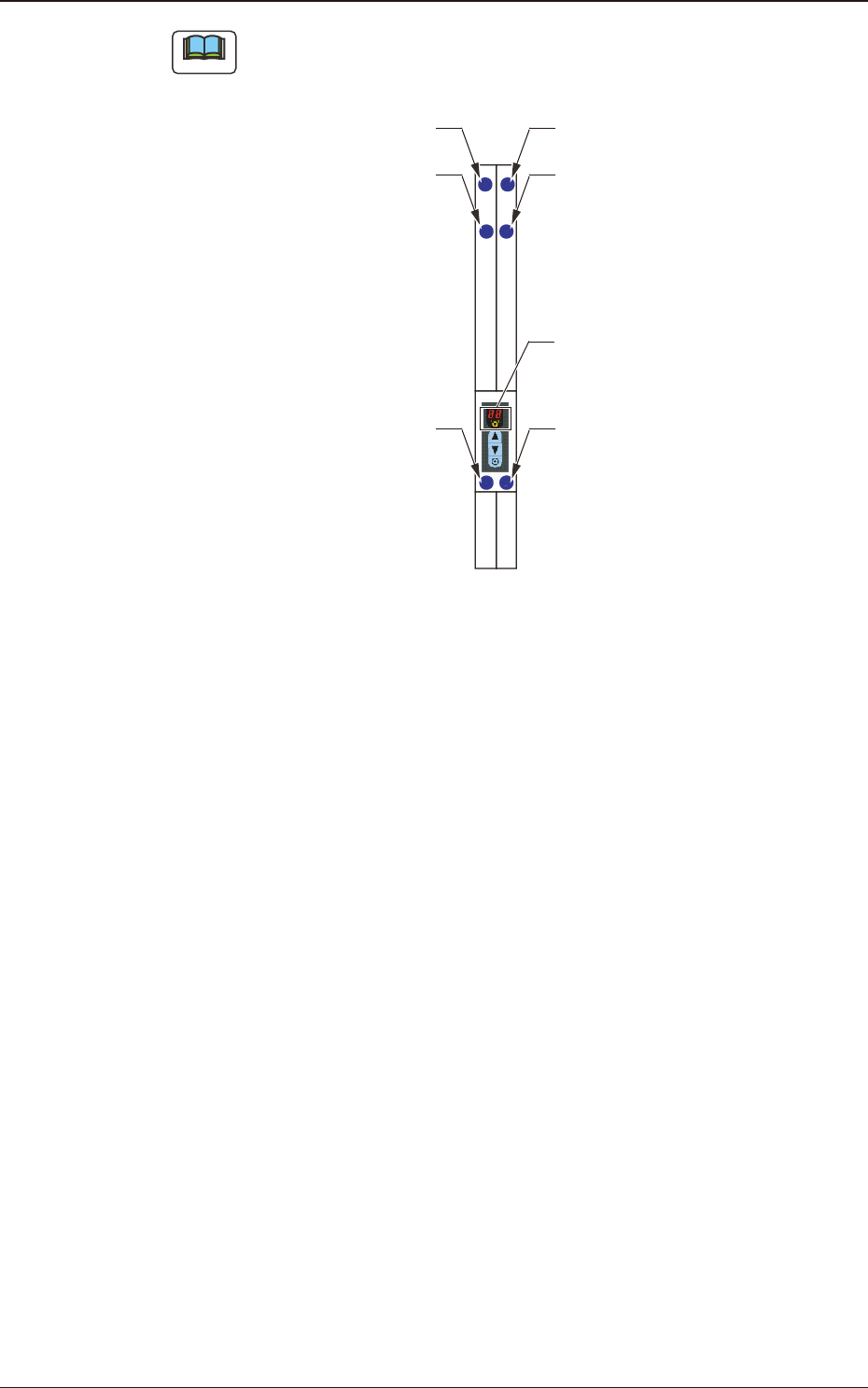
Note
The layout of the seven segments in the display section is arranged as the order
of the sensor arrangement on the feeder.
Lane 1 Sprocket Home Position
Detection Sensor
Lane #1 Tape Detection Sensor (2)
Lane #1 Tape
Detection Sensor (1)
Lane 2 Sprocket Home Position
Detection Sensor
Lane #2 Tape Detection Sensor (2)
Lane #2 Tape
Detection Sensor (1)
Seven Segments
Fig. D3
1504-001
4.2 Operation of Operation Panel
OM-1833
4-11

4.3 Error Code, Component Shortage Notication
If any error occurs during tape feeder operation, an error code is displayed on the
digital display.
Also, the component shortage notication is displayed.
•
Error codes are divided into two classications: one is
feeder operation error
with prex of "E", and the other is
servo alarm system error
with prex of
"A".
•
For the lane where an error has occurred, the dot display
is turned ON.
4.3.1 Feeder Operation Error Codes
[Detection Description] After the loading operation starts, even when the tape has been fed
with the specied amount, the tape end cannot be detected with the
tape detection sensor (2).
[Remedy] Press the loading button on the operation panel to clear the error
indication (EO).
[Cause and Remedy]
•
The loading suppressor in the tape guide section has not been
setup correctly.
⇒
Set it correctly.
•
A tape travel error occurs due to a catch, etc., during the loading
operation.
⇒
Check that there is no alien substance on the tape traveling surface
(chute).
•
The tape has not been set in the correct position.
⇒
Set the tape in the correct position.)
[Check Items]
•
Is the tape detection sensor (2) operating normally?
•
Is the loading motor (DC motor) rotating normally?
⇒
Motor malfunction (wire breakage, worn bush or commutator or damaged
shaft)
•
Broken Control PCB
E0 Loading Time-out
1504-001
4.3 Error Code, Component Shortage Notication
OM-1833
4-12