OM-1833-001w_SL.pdf - 第86页
1504-001 5.5.1.4 Left Side Cover #1 Attachment Procedure Procedure (1) Push the claws of the cover LD into the slits in the frame #2. Fig. E18 (2) Slide the cover LD in the arrow direction to set the claws under the othe…
1504-001
5.5.1.3 Cover LD Removal Procedure
Procedure
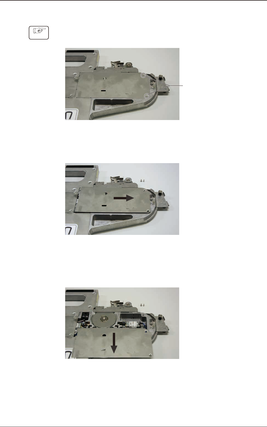
(1) Remove the countersunk screws xing the cover LD.
Countersunk Screw
(2 locations)
Fig. E15
(2) Slide the cover LD in the arrow direction (to the right).
Fig. E16
(3) Then, slide the cover LD in the arrow direction (lower) to remove the cover
LD.
Fig. E17
5.5 Maintenance Method
OM-1833
5-13
1504-001
5.5.1.4 Left Side Cover #1 Attachment Procedure
Procedure
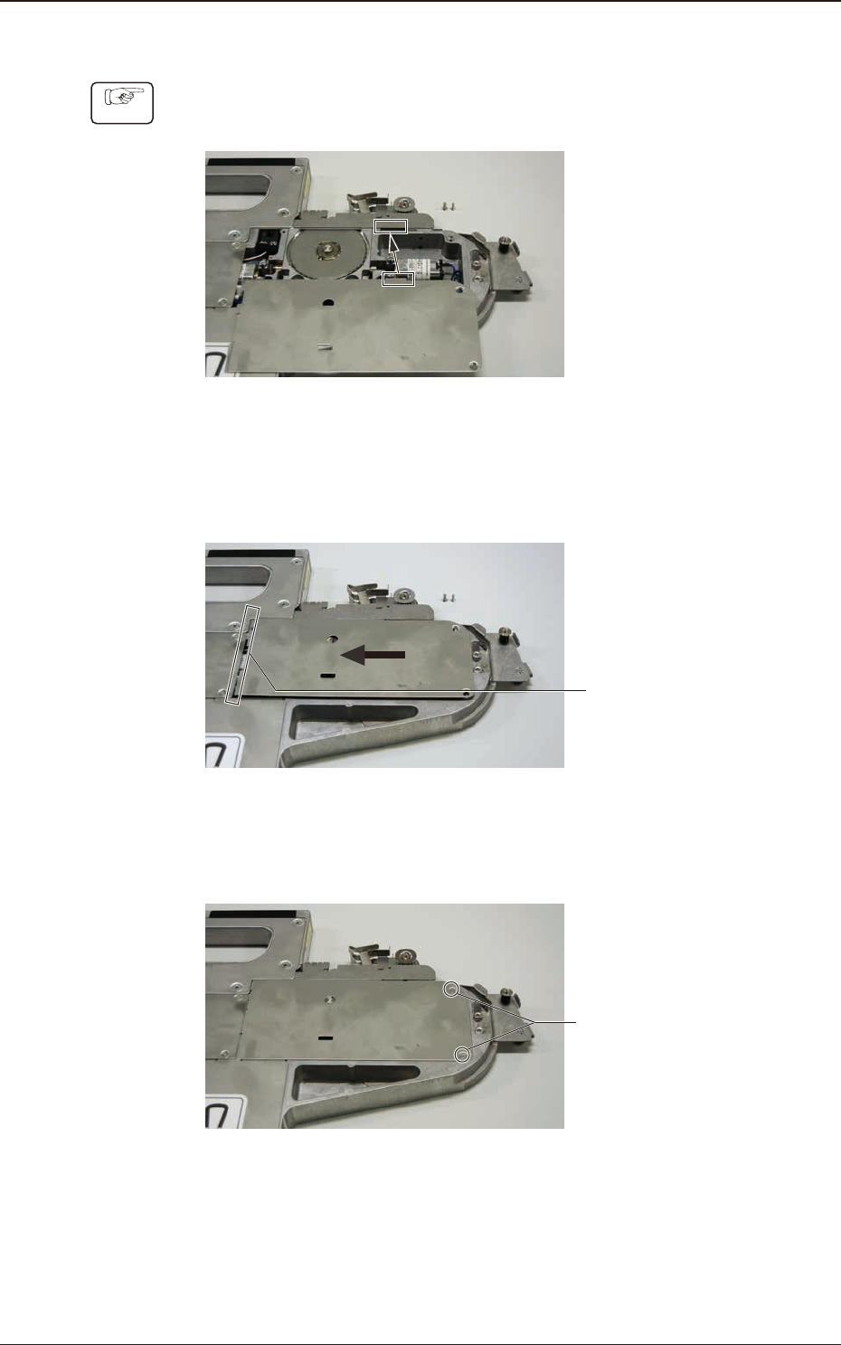
(1) Push the claws of the cover LD into the slits in the frame #2.
Fig. E18
(2) Slide the cover LD in the arrow direction to set the claws under the other
cover.
Set the
claws under it.
Fig. E19
(3) Attach the countersunk screws to x the cover LD (2 locations).
Countersunk Screw
(2 locations)
Fig. E20
5.5 Maintenance Method
OM-1833
5-14
1504-001
5.5.2 SL Taper Feeder Cutter Base Removal/Attachment
Notice
(a) A trained operator or service person should perform cleaning or
replacement of the cutter blades.
(b) There is a sharp projection at the rear of the cutter base that might
cause an injury.
5.5.2.1 Cutter Base Removal Procedure
Procedure
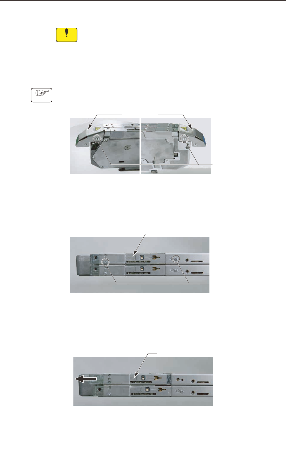
(1) Remove the countersunk screw xing the tape guide (2 locations)
Tape Guid
Countersunk Screw
(2 locations)
Fig. E21
(2) Remove the tape guide and remove the No. 0 round head screw xing the
cutter base (2 locations).
Cutter Base
No. 0 Round Head Screw
(2 locations)
Fig. E22
(3) Move the suppressor up and slide the cutter base in the arrow direction (to
the left) to remove.
Cutter Base
Fig. E23
5.5 Maintenance Method
OM-1833
5-15