00195679-02_AI_XPS_DE+EN.pdf - 第100页
7 Interface Description Assembly Instructions 7.3 AMI Interface Module SIPLACE X-Series Productivity Shuttle T y pe I/II 42 5. Remove the upper printed -circuit board carefully fro m the base. Figure 7 - 6 Opening the In…
41
Assembly Instructions 7 Interface Description
SIPLACE X-Series Productivity Shuttle Type I/II 7.3 AMI Interface Module
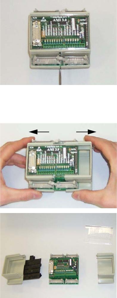
7.3.3 Opening the Interface Module
In order to set jumpers, the interface module must be opened as shown below.
1. Disconnect all connections from the interface module.
2. Remove the interface module from the bracket.
3. The housing is opened to the side. You can use a screwdriver to carefully open the fastener.
Figure 7 - 4 Opening the Interface Module - Figure 1
4. Pull the two parts of the housing towards the right and left.
Figure 7 - 5 Opening the Interface Module - Figures 2 and 3
7 Interface Description Assembly Instructions
7.3 AMI Interface Module SIPLACE X-Series Productivity Shuttle Type I/II
42
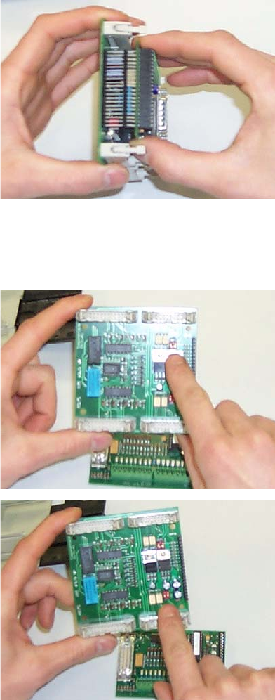
5. Remove the upper printed-circuit board carefully from the base.
Figure 7 - 6 Opening the Interface Module - Figure 4
6. You will find jumpers J4, J5, J6, and J7 on the lower printed-circuit board.
Figure 7 - 7 Opening the Interface Module - Figures 5 and 6
Reassemble the interface module in the reverse order.
43
Assembly Instructions 7 Interface Description
SIPLACE X-Series Productivity Shuttle Type I/II 7.4 SIM Interface Module
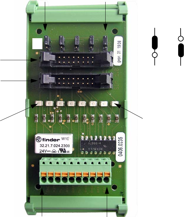
7.4 SIM Interface Module
The interface module is a SIM 1.0 (Smema Interface Module). It is used to connect the interfaces
of XPS to XPS to the controller of the XPL installed in the SIPLACE placement system.
7.4.1 Connection Diagram
Figure 7 - 8 SIM 1.0 Interface Module
X1.1
X1.2
X1.3
X1.4
X1.5
X1.6
X1.7
X1.8
X1.9
X1.10
X/N+1
X/N-1
JP1
JP2
JP3
JP4
JP5
LED X1.3
LED X1.10
GND
+24V
n. busy N-1
avail. N-1
pass N-1
n. busy N+1
avail. N+1
pass N+1
err lp out
err lp ret
ON
OFF
ON
OFF