00195679-02_AI_XPS_DE+EN.pdf - 第102页
7 Interface Description Assembly Instructions 7.4 SIM Interface Module SIPLACE X-Series Productivity Shuttle T ype I/II 44 7.4.2 Error Loop Function N+1 (first module): JP4 + JP5 ON ; JP1 - JP3 OFF N-1 / N+1 (middle modu…
43
Assembly Instructions 7 Interface Description
SIPLACE X-Series Productivity Shuttle Type I/II 7.4 SIM Interface Module
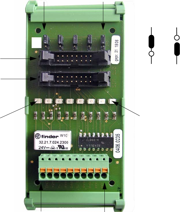
7.4 SIM Interface Module
The interface module is a SIM 1.0 (Smema Interface Module). It is used to connect the interfaces
of XPS to XPS to the controller of the XPL installed in the SIPLACE placement system.
7.4.1 Connection Diagram
Figure 7 - 8 SIM 1.0 Interface Module
X1.1
X1.2
X1.3
X1.4
X1.5
X1.6
X1.7
X1.8
X1.9
X1.10
X/N+1
X/N-1
JP1
JP2
JP3
JP4
JP5
LED X1.3
LED X1.10
GND
+24V
n. busy N-1
avail. N-1
pass N-1
n. busy N+1
avail. N+1
pass N+1
err lp out
err lp ret
ON
OFF
ON
OFF
7 Interface Description Assembly Instructions
7.4 SIM Interface Module SIPLACE X-Series Productivity Shuttle Type I/II
44
7.4.2 Error Loop Function
N+1 (first module): JP4 + JP5 ON; JP1 - JP3 OFF
N-1 / N+1 (middle module): JP2 + JP3 ON; JP1, JP4, JP5 OFF
N-1 (last module): JP1 ON; JP2 - JP5 OFF
Jumper (JP)
7.4.3 Indicator Lights
The eight LEDs correspond to terminal connections X1.3 to X1.10 as shown in Figure 7 - 8.
7.4.4 Plug Connectors
The 16-pin plug connectors X/N+1 and X/N-1 are the connections to the adjacent devices.
Explanation:
–X/N+1: Downstream machine
–X/N-1: Upstream machine
CAUTION
If the interfaces, i.e., the connections to the downstream and upstream machines (X/N+1 and X/
N-1), are swapped, the SMEMA interface (SIM 1.0) can be irrevocably damaged.
45
Assembly Instructions 8 Final Steps
SIPLACE X-Series Productivity Shuttle Type I/II
8 Final Steps
1. Thoroughly check the installation once again.
2. Are all cables connected and safely routed?
3. Are all parts remounted and securely attached?
4. Make sure that no tools or other parts have been left behind in the machines.