00195679-02_AI_XPS_DE+EN.pdf - 第69页
11 Assembly Instructions 3 Preliminary Work on the SIPLACE X-Series SIPLACE X-Series Productivity Shuttle T ype I/II 3.2 Routing and Connection of the Limit Switch Cable 8. Route the cable in the shaf t below the carrier…
3 Preliminary Work on the SIPLACE X-Series Assembly Instructions
3.2 Routing and Connection of the Limit Switch Cable SIPLACE X-Series Productivity Shuttle Type I/II
10
3.1.1 Required Part
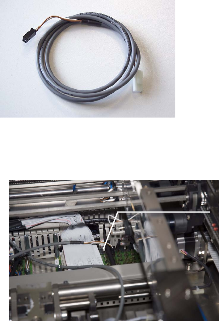
Cable/limit switch for XPL, Part number: 03065827-01
3.2 Routing and Connection of the Limit Switch Cable
7. Insert the cable for the SIPLACE X-Series onto the X7KU contact of the conveyor control.
X7KU transport control
11
Assembly Instructions 3 Preliminary Work on the SIPLACE X-Series
SIPLACE X-Series Productivity Shuttle Type I/II 3.2 Routing and Connection of the Limit Switch Cable
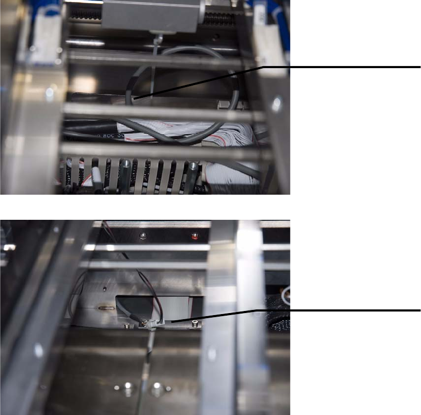
8. Route the cable in the shaft below the carrier unit of the intermediate conveyor of the SIPLACE
X-Series.
9. The connection to the XPL is made after the XPL is installed (see Chapter 4.2 Making Electrical
Connections).
10.Reinstall the cover over the main distributor of the conveyor control.
11.Before the lifting table plates can be reinstalled, the pneumatic cylinders of both lifting tables
must be depressurized and the linkage of the lifting tables must be lifted slightly.
12.Reinstall the lifting table plates in placement area 2.
Introduce cable into
the shaft via the cable
duct.
Guide cable through
the shaft. It will be
connected to the XPL
on the other side after
the XPL is installed.
3 Preliminary Work on the SIPLACE X-Series Assembly Instructions
3.2 Routing and Connection of the Limit Switch Cable SIPLACE X-Series Productivity Shuttle Type I/II
12