00195679-02_AI_XPS_DE+EN.pdf - 第76页
4 Installation of the XPL Assembly Instructions 4.3 Aligning the XPL SIPLACE X-Seri es Productivity Shuttle T y pe I/II 18 4. Now align the XPL laterally so that it runs in the ce nter be tween the two transp ort tracks …
17
Assembly Instructions 4 Installation of the XPL
SIPLACE X-Series Productivity Shuttle Type I/II 4.3 Aligning the XPL
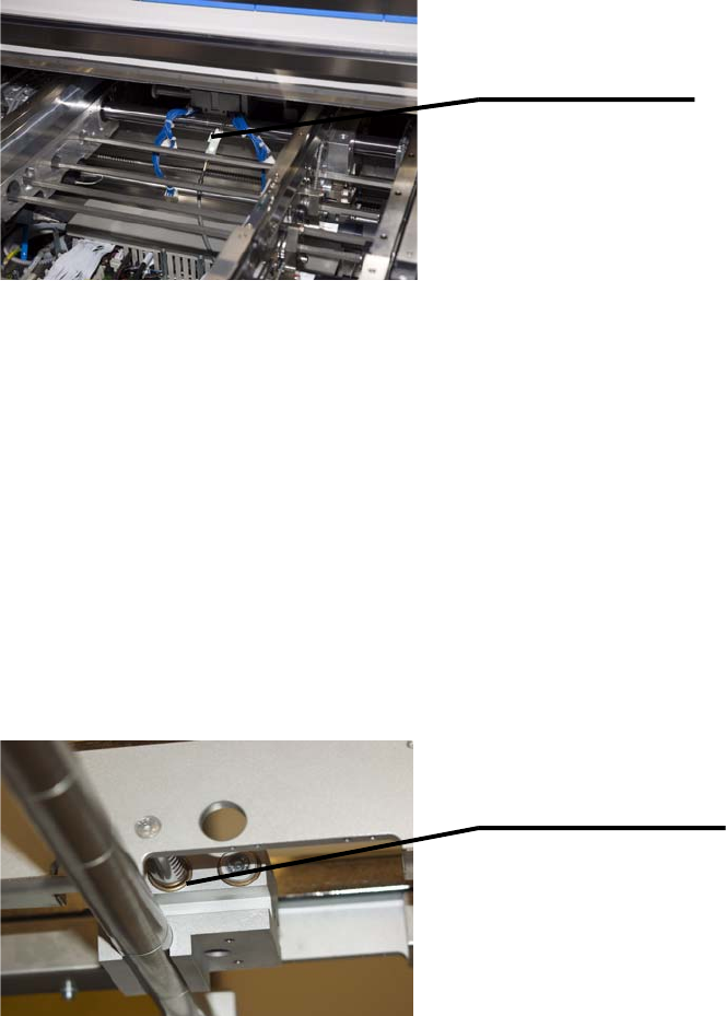
2. Connect the limit switch cable, which is already installed in the placement system, to the XPL.
4.3 Aligning the XPL
1. Switch on the SIPLACE X-Series again at the main switch.
NOTE
For better accessibility, the walls should be in position 268 and the machine should be
operated in the “Transport walls outside” or “Fixed rail outside” transport mode!
2. Adjust the width of both transport tracks of the SIPLACE X-Series to 152 mm.
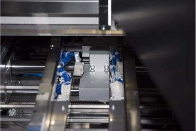
3. Push the two transport walls of the XPL apart up to the stop. Make sure that all three adjusting
units of the XPL are moved the maximum distance apart!
Connect limit switch
cable to XPL.
Adjusting unit of XPL
4 Installation of the XPL Assembly Instructions
4.3 Aligning the XPL SIPLACE X-Series Productivity Shuttle Type I/II
18
4. Now align the XPL laterally so that it runs in the center between the two transport tracks of the
SIPLACE X-Series and the limit switches are just short of being activated. Lightly tighten the
fastening screws.
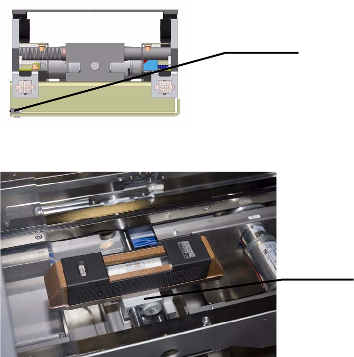
5. Now place the precision spirit level on the top of the shaft bearing of the XPL, as shown below.
6. Turn the shaft bearing until is leveled and then tighten the screws of the shaft clamping. This
adjusts the height of the XPL. Perform this adjustment on the inlet and outlet of the SIPLACE
X-Series. The placement system must have already been adjusted and aligned prior to this.
Limit switch
Shaft bearing
19
Assembly Instructions 4 Installation of the XPL
SIPLACE X-Series Productivity Shuttle Type I/II 4.3 Aligning the XPL
7. Now, tighten down the clamping screws that connect the two XPL parts.
8. Reinstall the covers at the inlet and outlet of the placement system.