00195679-02_AI_XPS_DE+EN.pdf - 第77页
19 Assembly Instructions 4 Installation of the XPL SIPLACE X-Series Productivity Shu ttle T ype I/II 4.3 Aligning the XPL 7. Now , tighten down the clamping screws that connect the two XPL p arts. 8. Reinstall the cove r…
4 Installation of the XPL Assembly Instructions
4.3 Aligning the XPL SIPLACE X-Series Productivity Shuttle Type I/II
18
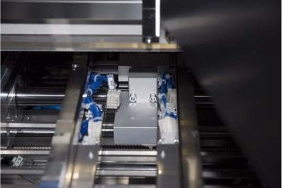
4. Now align the XPL laterally so that it runs in the center between the two transport tracks of the
SIPLACE X-Series and the limit switches are just short of being activated. Lightly tighten the
fastening screws.
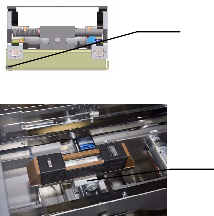
5. Now place the precision spirit level on the top of the shaft bearing of the XPL, as shown below.
6. Turn the shaft bearing until is leveled and then tighten the screws of the shaft clamping. This
adjusts the height of the XPL. Perform this adjustment on the inlet and outlet of the SIPLACE
X-Series. The placement system must have already been adjusted and aligned prior to this.
Limit switch
Shaft bearing
19
Assembly Instructions 4 Installation of the XPL
SIPLACE X-Series Productivity Shuttle Type I/II 4.3 Aligning the XPL
7. Now, tighten down the clamping screws that connect the two XPL parts.
8. Reinstall the covers at the inlet and outlet of the placement system.
4 Installation of the XPL Assembly Instructions
4.3 Aligning the XPL SIPLACE X-Series Productivity Shuttle Type I/II
20