00195679-02_AI_XPS_DE+EN.pdf - 第78页
4 Installation of the XPL Assembly Instructions 4.3 Aligning the XPL SIPLACE X-Seri es Productivity Shuttle T y pe I/II 20
19
Assembly Instructions 4 Installation of the XPL
SIPLACE X-Series Productivity Shuttle Type I/II 4.3 Aligning the XPL
7. Now, tighten down the clamping screws that connect the two XPL parts.
8. Reinstall the covers at the inlet and outlet of the placement system.
4 Installation of the XPL Assembly Instructions
4.3 Aligning the XPL SIPLACE X-Series Productivity Shuttle Type I/II
20
21
Assembly Instructions 5 Mounting the XPS
SIPLACE X-Series Productivity Shuttle Type I/II 5.1 Power Supply
5 Mounting the XPS
DANGER
Prior to starting work, verify that the SIPLACE X-Series and the XPS are switched off and
disconnected from the power supply system.
5.1 Power Supply
ATTENTION 5
Verify that the furnished power supply is compatible with the conditions at the installation site for
all Productivity Shuttles (XPS) to be installed.
The circuit diagram for each XPS is applicable in this regard.
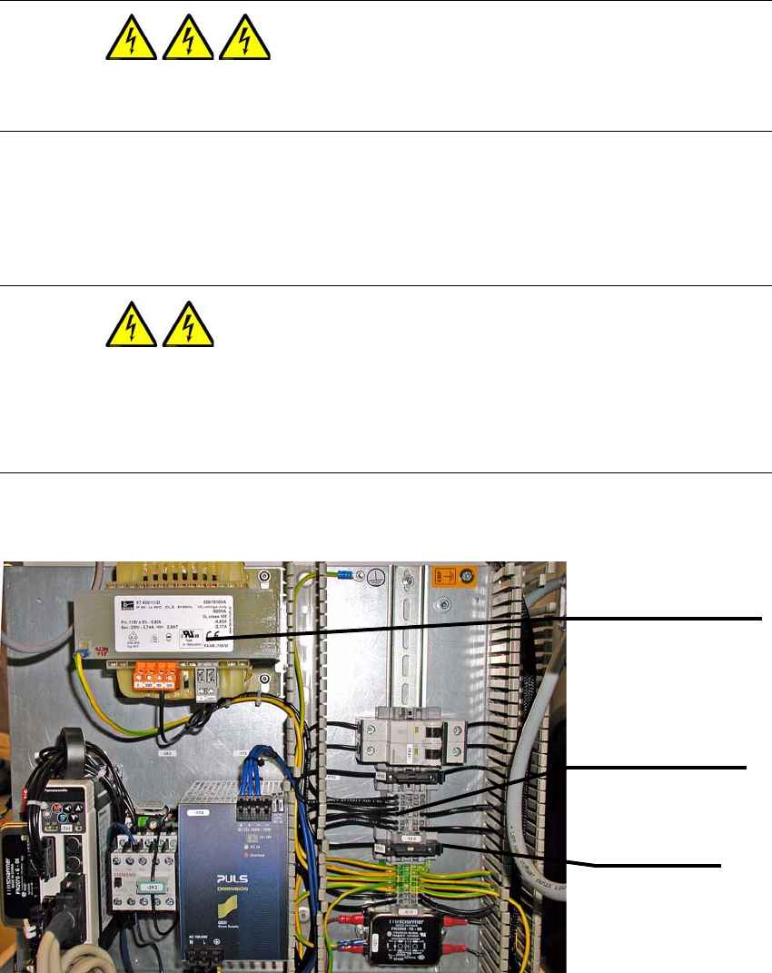
The figure below shows the wiring for the 230 V secondary voltage.
Terminal strip -X2.0
Terminals 1 to 6
Fuse -1F01
Fuse
Transformer -1T1
ST630-11-23 / 115 V AC