00195679-02_AI_XPS_DE+EN.pdf - 第80页
5 Mounting the XPS Assembly Instructi ons 5.1 Power Supply SIPLACE X-Seri es Productivity Shuttle T ype I/II 22 5.1.1 Converting to 1 15 V Secondary V oltage The figure below shows only a section of the circuit diagram. …
21
Assembly Instructions 5 Mounting the XPS
SIPLACE X-Series Productivity Shuttle Type I/II 5.1 Power Supply
5 Mounting the XPS
DANGER
Prior to starting work, verify that the SIPLACE X-Series and the XPS are switched off and
disconnected from the power supply system.
5.1 Power Supply
ATTENTION 5
Verify that the furnished power supply is compatible with the conditions at the installation site for
all Productivity Shuttles (XPS) to be installed.
The circuit diagram for each XPS is applicable in this regard.
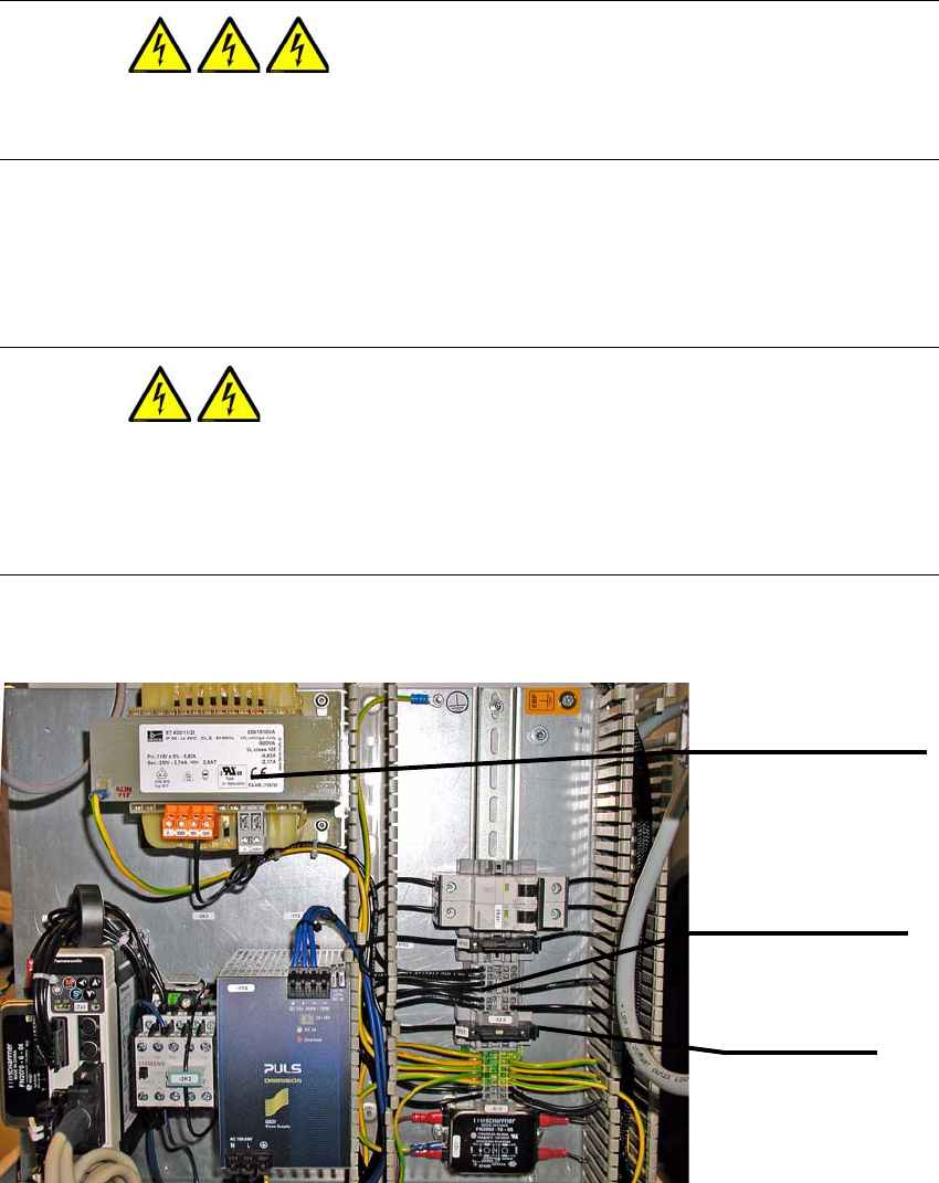
The figure below shows the wiring for the 230 V secondary voltage.
Terminal strip -X2.0
Terminals 1 to 6
Fuse -1F01
Fuse
Transformer -1T1
ST630-11-23 / 115 V AC
5 Mounting the XPS Assembly Instructions
5.1 Power Supply SIPLACE X-Series Productivity Shuttle Type I/II
22
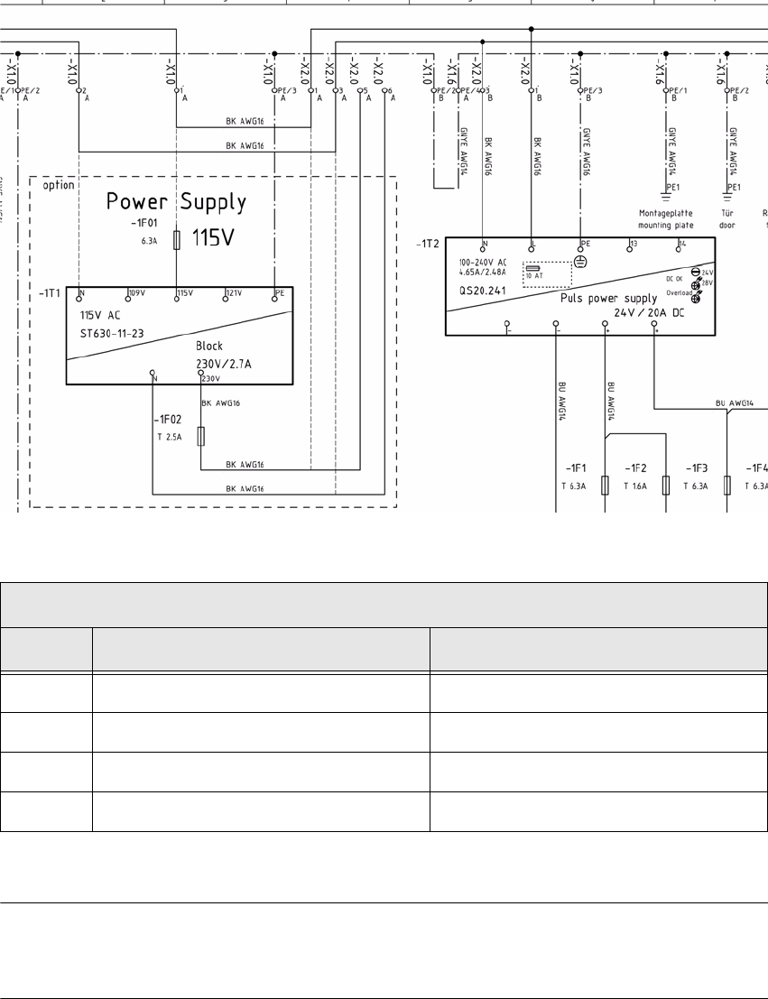
5.1.1 Converting to 115 V Secondary Voltage
The figure below shows only a section of the circuit diagram. To convert from 230 V to 115 V, refer
to the applicable circuit diagram for the machine.
NOTE 5
For conversion to 115 V, a suitable power plug for the country must be used.
Changing the terminal connections
Step From To
1 Terminal strip -X2.0, Terminal 1 Fuse -1F01
2 Terminal strip -X2.0, Terminal 3 Transformer -1T1, N
3 Terminal strip -X2.0, Terminal 5 Terminal strip -X2.0, Terminal 1
4 Terminal strip -X2.0, Terminal 6 Terminal strip -X2.0, Terminal 3
Table: Converting to 115 V secondary voltage
23
Assembly Instructions 5 Mounting the XPS
SIPLACE X-Series Productivity Shuttle Type I/II 5.2 XPS at the Inlet of the Placement System
5.2 XPS at the Inlet of the Placement System
1. Install the SIPLACE X-Series Productivity Shuttle (XPS) at the inlet of the placement system,
allowing enough distance that the cables can be connected problem-free. The operator panel
of the XPS is located on the right side when viewed in the direction of travel.
NOTE
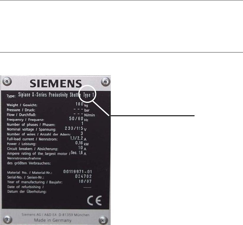
If provision is made for the line for combined mode and there are XPSs of different types,
attention must be paid that one XPS of Type I is located at the start (start module) and end
(end module) of the line.
Pay attention to the label on the name plate.
Type label