00195679-02_AI_XPS_DE+EN.pdf - 第82页
5 Mounting the XPS Assembly Instructi ons 5.2 XPS at the Inlet of the Placement System SIPLACE X-Series Productivity Shuttle T ype I/II 24 2. Mount the supplied rubbe r plates on the bottom of the adjust able feet. Make …
23
Assembly Instructions 5 Mounting the XPS
SIPLACE X-Series Productivity Shuttle Type I/II 5.2 XPS at the Inlet of the Placement System
5.2 XPS at the Inlet of the Placement System
1. Install the SIPLACE X-Series Productivity Shuttle (XPS) at the inlet of the placement system,
allowing enough distance that the cables can be connected problem-free. The operator panel
of the XPS is located on the right side when viewed in the direction of travel.
NOTE
If provision is made for the line for combined mode and there are XPSs of different types,
attention must be paid that one XPS of Type I is located at the start (start module) and end
(end module) of the line.
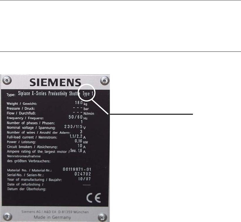
Pay attention to the label on the name plate.
Type label
5 Mounting the XPS Assembly Instructions
5.2 XPS at the Inlet of the Placement System SIPLACE X-Series Productivity Shuttle Type I/II
24
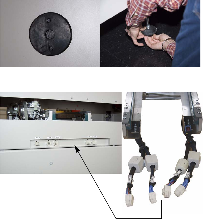
2. Mount the supplied rubber plates on the bottom of the adjustable feet. Make appropriate use
of a lift truck for this purpose.
3. Electrically connect the XPS to the XPL.
Connect according to the marking.
25
Assembly Instructions 5 Mounting the XPS
SIPLACE X-Series Productivity Shuttle Type I/II 5.2 XPS at the Inlet of the Placement System
4. Now place the XPS next to the placement machine. The front edges of the XPS and placement
machine should be flush with placement space 1. Leave a small gap of approximately 3
mm
between the machines to avoid transmission of vibrations.
NOTE
Use the lift truck. With rubber plates installed on the adjustable feet, the XPS can be moved
only with great difficulty.
Gap, approximately 3 mm
Front edge flush