00195679-02_AI_XPS_DE+EN.pdf - 第85页
27 Assembly Instructions 5 Mounting the XPS SIPLACE X-Series Productivity S huttle T ype I/II 5.4 Aligning the XPS 5.4 Aligning the XPS The transport height of all XPSs must now be adju sted to the transport height of th…

5 Mounting the XPS Assembly Instructions
5.3 XPS at the Outlet of the Placement System SIPLACE X-Series Productivity Shuttle Type I/II
26
5.3 XPS at the Outlet of the Placement System
1. Install the XPS at the outlet of the placement system, allowing enough distance that you can
mount the rubber plates problem-free. The operator panel of the XPS is located on the right
side when viewed in the direction of travel.
NOTE
If provision is made for the line for combined mode and there are XPSs of different types,
attention must be paid that one XPS of Type I is located at the start (start module) and end
(end module) of the line. The intermediate module can be a Type II XPS.
Pay attention to the label on the name plate.
2. Mount the supplied rubber plates on the bottom of the adjustable feet. Make appropriate use
of a lift truck for this purpose.
3. Now place the XPS next to the placement machine. The front edges of the XPS and placement
machine should be flush with the outlet placement space 2. Leave a small gap of
approximately 3
mm between the machines to avoid transmission of vibrations.
NOTE
Use the lift truck. With rubber plates installed on the adjustable feet, the XPS can be moved
only with great difficulty.
27
Assembly Instructions 5 Mounting the XPS
SIPLACE X-Series Productivity Shuttle Type I/II 5.4 Aligning the XPS
5.4 Aligning the XPS
The transport height of all XPSs must now be adjusted to the transport height of the placement
system. Make the following adjustments for Track 1 and Track 2.
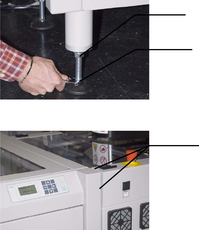
1. Start by roughly adjusting the height of the XPS. For this purpose, loosen the lock nuts on the
adjustable feet and turn the feet with the adjustment nuts in the appropriate direction.
The XPS should be flush with the placement system at the front and top.
Lock nut
Adjustment
Roughly flush
5 Mounting the XPS Assembly Instructions
5.4 Aligning the XPS SIPLACE X-Series Productivity Shuttle Type I/II
28
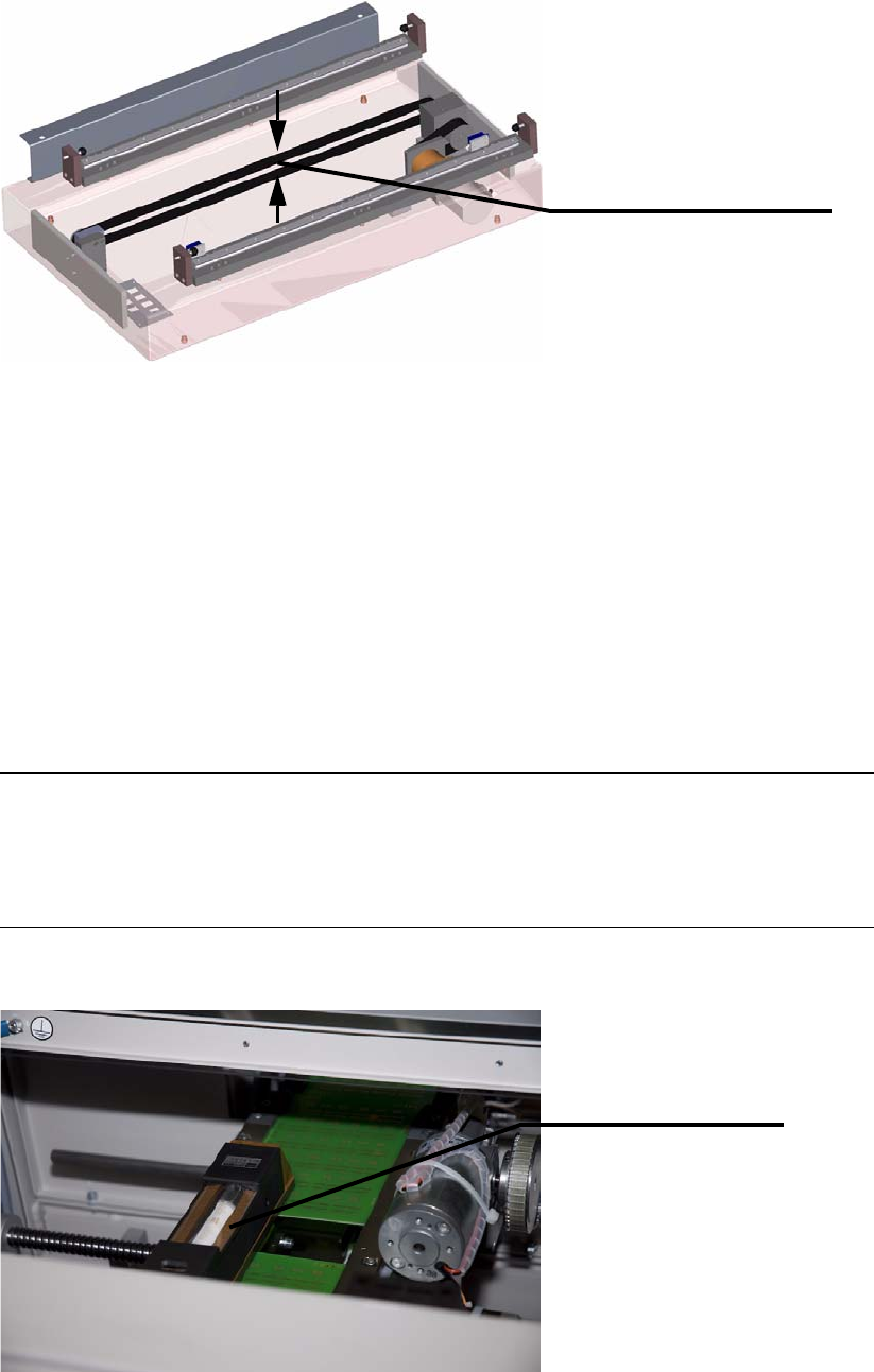
2. Remove the transport lock on the shuttle.
3. Connect the XPS to the power supply system and switch it on at the main switch.
4. The SIPLACE X-Series can now be switched on again if required, for example, to adjust the
transport width.
5. Start with Track 1. Manually move the shuttle conveyor of the XPS to the appropriate position;
the fixed stops of both conveyors must match up. Refer to the operating manual for the XPS
for this.
6. Place two printed-circuit boards on the shuttle conveyor and one printed-circuit board on Track
1 of the inlet/outlet conveyor of the placement system. Place the precision spirit level on the
printed-circuit boards on the shuttle conveyor.
NOTE
The widths of both machines should be adjusted to the width of the printed-circuit boards you
are using for this adjustment. Follow the procedure for this in the operating manuals for the
machines.
The shuttle is secured for
transport.
The toothed drive belt is
held together with a clamp.
Precision spirit level