00195679-02_AI_XPS_DE+EN.pdf - 第86页
5 Mounting the XPS Assembly Instructi ons 5.4 Aligning the XPS SIPLACE X-Seri es Productivity Shuttle T ype I/II 28 2. Remove the transport lock on the shuttle. 3. Connect the XPS to the power supply system and switch it…
27
Assembly Instructions 5 Mounting the XPS
SIPLACE X-Series Productivity Shuttle Type I/II 5.4 Aligning the XPS
5.4 Aligning the XPS
The transport height of all XPSs must now be adjusted to the transport height of the placement
system. Make the following adjustments for Track 1 and Track 2.
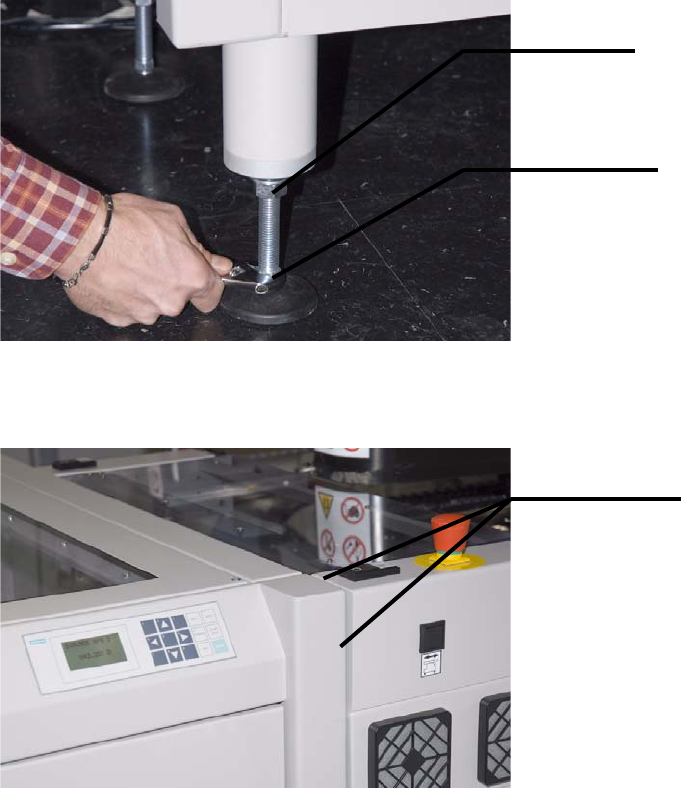
1. Start by roughly adjusting the height of the XPS. For this purpose, loosen the lock nuts on the
adjustable feet and turn the feet with the adjustment nuts in the appropriate direction.
The XPS should be flush with the placement system at the front and top.
Lock nut
Adjustment
Roughly flush
5 Mounting the XPS Assembly Instructions
5.4 Aligning the XPS SIPLACE X-Series Productivity Shuttle Type I/II
28
2. Remove the transport lock on the shuttle.
3. Connect the XPS to the power supply system and switch it on at the main switch.
4. The SIPLACE X-Series can now be switched on again if required, for example, to adjust the
transport width.
5. Start with Track 1. Manually move the shuttle conveyor of the XPS to the appropriate position;
the fixed stops of both conveyors must match up. Refer to the operating manual for the XPS
for this.
6. Place two printed-circuit boards on the shuttle conveyor and one printed-circuit board on Track
1 of the inlet/outlet conveyor of the placement system. Place the precision spirit level on the
printed-circuit boards on the shuttle conveyor.
NOTE
The widths of both machines should be adjusted to the width of the printed-circuit boards you
are using for this adjustment. Follow the procedure for this in the operating manuals for the
machines.
The shuttle is secured for
transport.
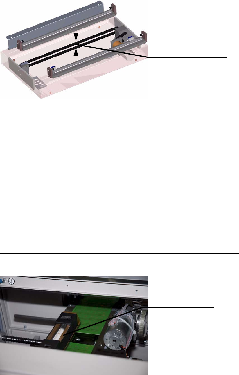
The toothed drive belt is
held together with a clamp.
Precision spirit level
29
Assembly Instructions 5 Mounting the XPS
SIPLACE X-Series Productivity Shuttle Type I/II 5.5 Cover over the Transfer Openings
7. Adjust the adjustable feet so that the XPS is in the water and the printed-circuit boards can be
slid from the shuttle conveyor onto Track 1 of the placement system without tipping and
colliding.
8. Repeat the procedure for Track 2.
9. Check the adjustments for tracks 1 and 2 again and make corrections as necessary.
10.Remove the printed-circuit boards used for the adjustment and the precision spirit level.
11.Switch off the XPS again at the main switch and disconnect it from the power supply system.
5.5 Cover over the Transfer Openings
The transfer opening on the SIPLACE X-Series Productivity Shuttle (XPS) must always be
covered with the plates provided, except for the necessary printed-circuit board width. This applies
to the input module (at the inlet), the end module (at the outlet) and every transfer opening of each
XPS that does not adjoin a SIPLACE placement system.
Figure 5 - 1 Cover over the Transfer Openings: Minimum Printed-Circuit Board Width
Attach the cover plate according to the your requirements (printed-circuit board width).
Minimum printed-
circuit board width
Input module,
view in pass-
through direction