00195679-02_AI_XPS_DE+EN.pdf - 第88页
5 Mounting the XPS Assembly Instructi ons 5.5 Cover over the T ransfer Openings SIPLAC E X-Series Productivity Shuttle T ype I/II 30 The cover plates are both the same size . The openi ng width is adjusted by means of th…
29
Assembly Instructions 5 Mounting the XPS
SIPLACE X-Series Productivity Shuttle Type I/II 5.5 Cover over the Transfer Openings
7. Adjust the adjustable feet so that the XPS is in the water and the printed-circuit boards can be
slid from the shuttle conveyor onto Track 1 of the placement system without tipping and
colliding.
8. Repeat the procedure for Track 2.
9. Check the adjustments for tracks 1 and 2 again and make corrections as necessary.
10.Remove the printed-circuit boards used for the adjustment and the precision spirit level.
11.Switch off the XPS again at the main switch and disconnect it from the power supply system.
5.5 Cover over the Transfer Openings
The transfer opening on the SIPLACE X-Series Productivity Shuttle (XPS) must always be
covered with the plates provided, except for the necessary printed-circuit board width. This applies
to the input module (at the inlet), the end module (at the outlet) and every transfer opening of each
XPS that does not adjoin a SIPLACE placement system.
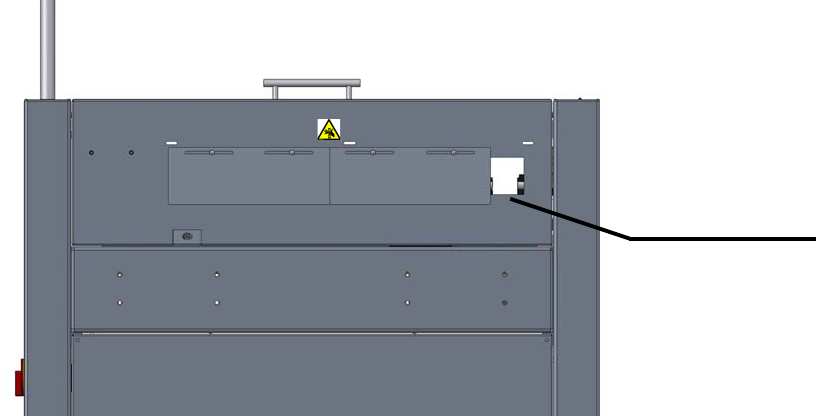
Figure 5 - 1 Cover over the Transfer Openings: Minimum Printed-Circuit Board Width
Attach the cover plate according to the your requirements (printed-circuit board width).
Minimum printed-
circuit board width
Input module,
view in pass-
through direction
5 Mounting the XPS Assembly Instructions
5.5 Cover over the Transfer Openings SIPLACE X-Series Productivity Shuttle Type I/II
30
The cover plates are both the same size. The opening width is adjusted by means of the oblong
holes and, if required, by shifting over one screw hole.
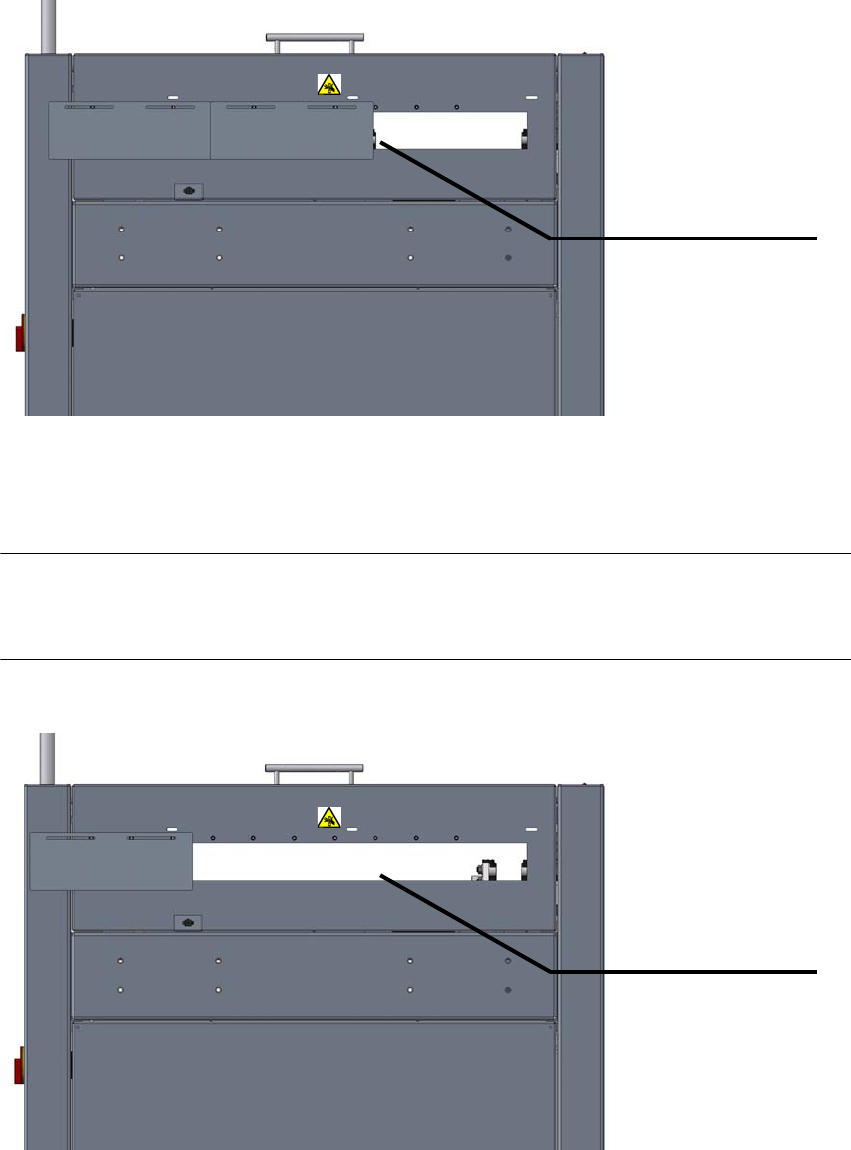
Figure 5 - 2 Cover over the Transfer Openings: Maximum Printed-Circuit Board Width
The opening is opened up to the maximum. Both plates are kept in the position shown below.
NOTE
This adjustment is only permissible for the intermediate module and cross module equipment
types, that is, these XPSs are located between two SIPLACE placement systems.
Figure 5 - 3 Cover over the Transfer Openings: Maximum Opening Width
Maximum printed-
circuit board width
Input module,
view in pass-
through direction
Maximum opening
Intermediate
module,
view in pass-through
direction
31
Assembly Instructions 5 Mounting the XPS
SIPLACE X-Series Productivity Shuttle Type I/II 5.6 Safety Cover
5.6 Safety Cover
NOTE 5
The safety cover is a component of the SIPLACE XPS Accessory Package 1, part no. 00119974,
and must be ordered separately, when required.
The safety officer of the operator must determine whether it is required.
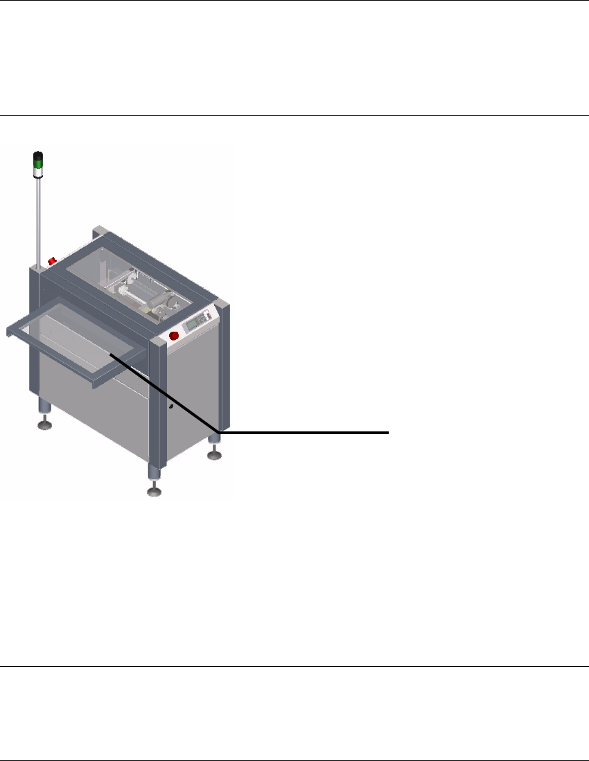
Figure 5 - 4 Safety cover
5.6.1 Purpose
The safety cover is used to secure the transfer opening between the input and output modules
and adjacent machines, such as
a conveyor belt (ideally, an ASYS TRM), against interventions.
NOTE 5
The safety cover is not a universal cover that is suitable for every possible type of adjacent
equipment. A special cover may be necessary in some cases.
Safety cover