00195679-02_AI_XPS_DE+EN.pdf - 第90页
5 Mounting the XPS Assembly Instructi ons 5.6 Safety Cover SIPLACE X-Seri es Productivity Shuttle T ype I/II 32 5.6.2 Inst allation NOTE 5 The safety co ver must not be inst alled as a self -suppo rting cover under any c…
31
Assembly Instructions 5 Mounting the XPS
SIPLACE X-Series Productivity Shuttle Type I/II 5.6 Safety Cover
5.6 Safety Cover
NOTE 5
The safety cover is a component of the SIPLACE XPS Accessory Package 1, part no. 00119974,
and must be ordered separately, when required.
The safety officer of the operator must determine whether it is required.
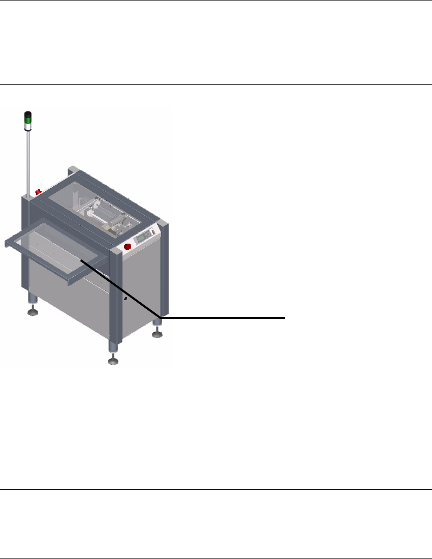
Figure 5 - 4 Safety cover
5.6.1 Purpose
The safety cover is used to secure the transfer opening between the input and output modules
and adjacent machines, such as
a conveyor belt (ideally, an ASYS TRM), against interventions.
NOTE 5
The safety cover is not a universal cover that is suitable for every possible type of adjacent
equipment. A special cover may be necessary in some cases.
Safety cover
5 Mounting the XPS Assembly Instructions
5.6 Safety Cover SIPLACE X-Series Productivity Shuttle Type I/II
32
5.6.2 Installation
NOTE 5
The safety cover must not be installed as a self-supporting cover under any circumstances. It's
design calls for the cover to rest on the adjacent conveyor module.
If this is not possible, this cover is not suitable and must be replaced by a special cover.
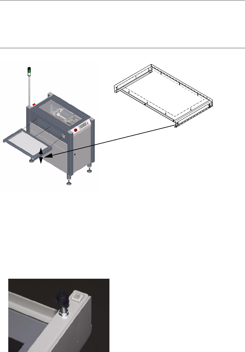
Figure 5 - 5 Installing the safety cover
1. The safety cover is attached to the XPS using three hexagon socket head cap screws M4x12
DIN
912. The screws are included with the cover.
2. The side parts of the cover are height-adjustable. The setting range is 24 mm. This adjustment
must be used to ensure that the cover rests on the conveyor belt.
3. If 24 mm is not sufficient, the spacing bolts shown in the figure can be used in the M4 thread
on the bottom of the side parts. These parts are not included in the scope of delivery.
33
Assembly Instructions 6 Making the Interface Connections
SIPLACE X-Series Productivity Shuttle Type I/II
6 Making the Interface Connections
For one thing, the interface connection from the XPS to the placement system and from the XPS
to the XPS must be made.
NOTE
Note the interface description in Chapter Interface Description and the circuit diagram
documentation for the XPS.
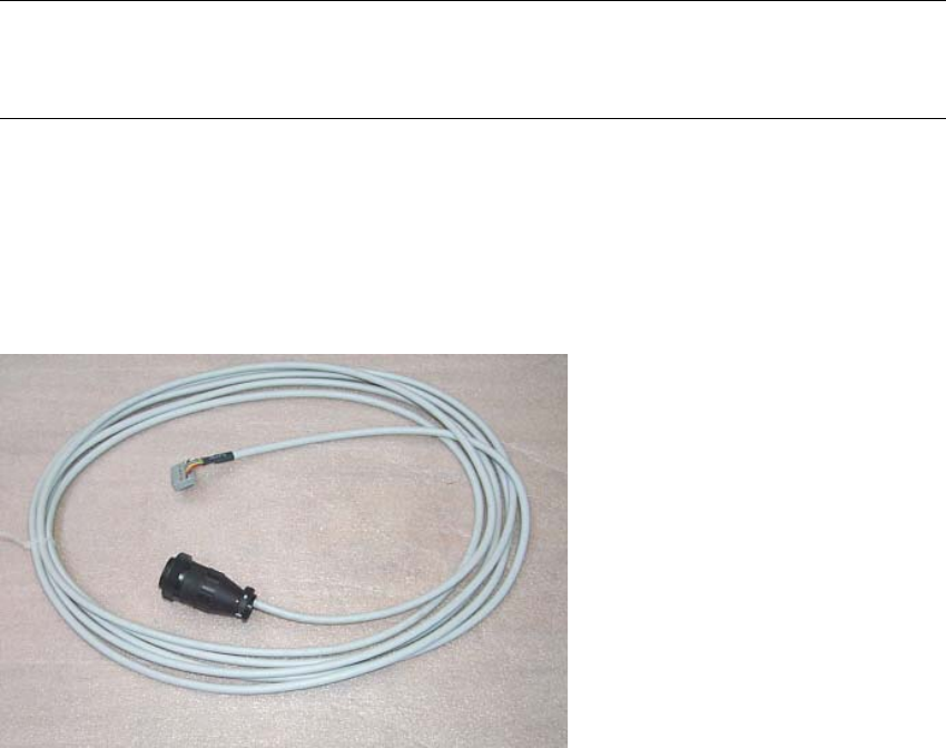
The following SMEMA interface cables are included in the delivery:
3x 00353086-02 l = 5 m, 1x socket connector 16-pin, 1x CPC
3x 00365032-02 l = 5 m, 1x socket connector 16-pin, 1x CPC